ICA-HM240
ICA-HM240
their respective owners. Copyright © 2010 PLANET Technology Corp. All rights reserved.
PLANET Technology Corporation
11F, No. 96, Min Chuan Road, Hsin Tien, Taipei, Taiwan, R.O.C.
Tel: 886-2-2219-9518
Fax: 886-2-2219-9528
Email: [email protected]
www.planet.com.tw
Quick Guide
Quick Guide
2011-AB5340-001
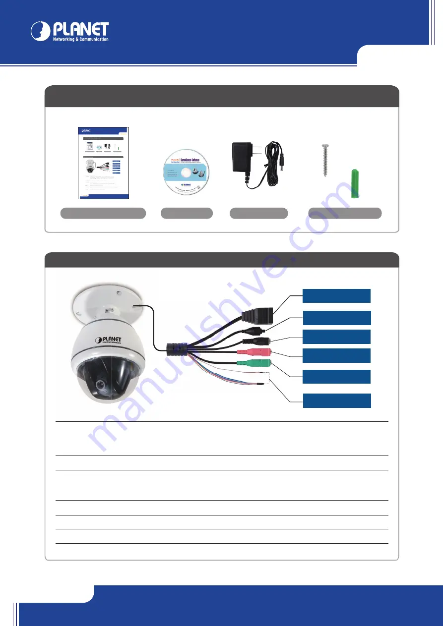
1. LAN Socket
2. Reset Button
3. Power Jack
4. MIC in
5. Line out
6. DI/DO
VERIFY THE CONTENTS INSIDE PACKAGE BOX
The package should contain the items plus ICA-HM240. If any item is missing or damaged, please contact the seller immediately
Power Adapter
CD-ROM
Camera Mounting Kit
Quick Installation Guide
Note :
Use the power adapter, 12VDC, included in the package and connect it to wall outlet for AC power
1-a. Plug an Ethernet cable into the IP Camera
Step 1 : Connecting Network and AC Adapter Power
Connect an Ethernet cable to the LAN socket and attach it to the network. When this switch/hub is a PoE device, you can ignore the next
step.
1-b. Connect the external power supply to IP Camera
Connect the attached power adapter to the DC power jack of the IP Camera.
Once you have installed the IP Camera well and powered it on, the power indicator (orange) will turn on later. The power indicator turned on,
it means the system is booting up successfully. Furthermore, if you have a proper network connection, and access to the camera, the LAN
indicator (green) will flash.
Step 2 : Computer Network Setup
2.1 If there is DHCP server existed in the network, please refer to the
DHCP server IP table for the IP of the camera.
2.2 If there is no DHCP server, set your computer’s IP address to
192.168.0.x, where x is an integer between 1 to 254 (except 20
where is being used for the camera by default).
2.3 Or install the wizard utility to search the camera.
ICA-HM240 Physical Detail
ICA-HM240
Ethernet Switch
User PC
(192.168.0.X)
Further Configuration
For detail configuration, please check user’s manual on the bundled CD.
If you have any other questions, please contact the dealer where you purchased this product or you can contact PLANET directly at the following
email address: [email protected]
Step 3 : Login Prompt
1. LAN socket
Please use CAT-5 cable to connect the IP Camera to a 10/100Mbps Ethernet switch or hub.
LAN LED (Green)
: This indicator will be flashing while network accessing via Ethernet.
Power LED (Orange)
: This indicator is used to indicate whether DC power is on or not.
2. Reset Button
This button is used to restore the all factory default settings.
3. Power Jack
The input power is 12VDC
Note :
1. Supply the power to the IP Camera with the power adapter included in package.
2. Use either 12VDC power or 802.3af PoE. Please do not apply both at the same time.
4. MIC IN
Please connect a microphone to the IP Camera.
5. Line Out
Please connect a loud speaker to the IP Camera. This function is for voice alerting and two-way audio.
6. DI/DO
Please connect to sensor in and alarm out equipment.
x 3
x 3
Start the web browser on the computer and type the IP address of the
camera, and the Default IP:
“http://192.168.0.20”
You’ll be prompted to input user name and password: admin / null
(without password)


