

- 1 -
- 2 -
- 3 -
- 4 -
- 5 -
- 6 -
- 7 -
- 8 -
1. Package Contents
Check the following contents of your package:
If any of these are missing or damaged, please contact
your dealer immediately; if possible, retain the carton
including the original packing material, and use them
again to repack the product in case there is a need to
return it to us for repair.
GSD-604HP
User's Manual
55V Power Adapter
Power Cord
Rubber Feet
Wall-mount Kit
x 4
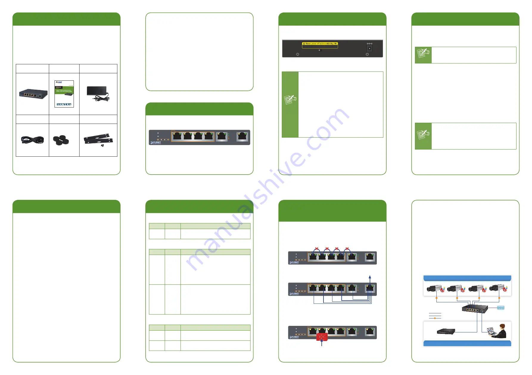
5. Switch Rear Panel
Figure 5-1 shows the rear panel of GSD-604HP.
55V DC
Disable
Enable
Port-based VLAN & Loop protection
Please power off before switching DIP.
Figure 5-1:
GSD-604HP Rear Panel
Power
Notice
1. The device is a power-required device,
meaning it will not work till it is pow-
ered. If your networks should be active
all the time, please consider using UPS
(Uninterrupted Power Supply) for your
device. It will prevent you from network
data loss or network downtime.
2. In some areas, installing a surge sup-
pression device may also help to protect
your GSD-604HP from being damaged
by unregulated surge or current to the
GSD-604HP or the power adapter
2. Product Features
RJ45 Interface
6 10/100/1000Mbps Gigabit Ethernet ports
4 ports support 54V DC power to PoE powered
device
Power over Ethernet
Complies with IEEE 802.3af/at Power over Ethernet
end-span PSE
Up to 4 IEEE 802.3af/802.3at devices powered
Supports PoE power up to 30 watts for each PoE
port
55-watt PoE Budget
Auto detects powered device (PD)
Circuit protection prevents power interference
between ports
Remote power feeding up to 100m
Hardware
LED indicators for PoE ready/activity and LINK/ACT
One 55V DC power jack
Switching
Hardware based 10/100/1000Mbps auto-negotiation
and auto MDI/MDI-X
Flow control for full duplex operation and back
pressure for half duplex operation
9216 bytes jumbo packet size support
Integrates address look-up engine, supporting 8K
absolute MAC addresses
Automatic address learning and address aging
Supports port-based VLAN and loop protection
3. Switch Front Panel
Figure 3-1 shows the front panel of GSD-604HP.
PWR
PoE MAX
PoE In-Use
1
2
3
4
GSD-604HP
5
Uplink
4
1
2
3
6
PoE
ACT
1000 LNK
ACT
10/100 LNK
Figure 3-1:
GSD-604HP Front Panel
6. Port-based VLAN and Loop
Protection Feature
The GSD-604HP has one feature called Port-based
VLAN and Loop Protection. When switching the DIP to
the “Enable” position, port 1 to port 5 wouldn’t able to
communicate with each other.
PWR
PoE MAX
PoE In-Use
1
2
3
4
GSD-604HP
5
Uplink
4
1
2
3
6
PoE
ACT
1000 LNK
ACT
10/100 LNK
Port 1 to Port 5 only can communicate with Uplink Port 6.
PWR
PoE MAX
PoE In-Use
1
2
3
4
GSD-604HP
5
Uplink
4
1
2
3
6
PoE
ACT
1000 LNK
ACT
10/100 LNK
When there is a loop happening from the client, the
GSD-604HP will block that port and wouldn’t allow data
to transfer to the switch.
PWR
PoE MAX
PoE In-Use
1
2
3
4
GSD-604HP
5
Uplink
4
1
2
3
6
PoE
ACT
1000 LNK
ACT
10/100 LNK
Loop (broadcast)
4. LED Indicators
System
LED
Color
Function
PWR
Green
Lights:
Indicates the Switch has
power.
Per 10/100/1000Mbps Port
LED
Color
Function
1000
LNK
Green
Lights:
Indicates the link through
that port is successfully
established at 1000Mbps.
Blinks:
Indicates that the Switch is
actively sending or receiving
data over that port.
10/100
LNK
Orange
Lights:
Indicates the link through
that port is successfully
established at 10/100Mbps.
Blinks:
Indicates that the Switch is
actively sending or receiving
data over that port.
PoE-in-Use Port
LED
Color
Function
PoE
Orange
Lights:
Indicates the port is providing
54V DC in-line power.
MAX
Orange
Lights:
80% of PoE usage
Blinks:
100% of PoE usage
7. Installing the Switch
This part describes how to install your Gigabit PoE+
Switch and make connections to it. Please read the
following topics and follow the procedures as presented.
Note
This Gigabit PoE+ Switch does not need
software configuration.
Desktop Installation
To install the Gigabit PoE+ Switch on desktop, simply
follow the following steps:
Step 1:
Attach the rubber feet to the recessed areas
on the bottom of the Gigabit PoE+ Switch.
Step 2:
Place the Gigabit PoE+ Switch on desktop near
AC power source for its power adapter.
Step 3:
Keep enough ventilation space between the
Gigabit PoE+ Switch and the surrounding
objects.
Note
When choosing a location, please keep in
mind the environmental restrictions dis-
cussed in Chapter 8 -- Product Specifica-
tions.
Step 4:
Connect your Gigabit PoE+ Switch to network
devices.
A.
Connect one end of a standard network cable to
port-5 and port-6 10/100/1000Mbps RJ45 ports on
the front of the Gigabit PoE+ Switch.
B.
Connect the other end of the cable to the network
devices such as NVR(Network Video Recorder),
workstations or routers.
Step 5:
Connect your Gigabit PoE+ Switch to PoE PD
devices.
A.
Connect one end of a standard network cable to port
1 to port 4 10/100/1000Mbps RJ45 ports on the
Front of the Gigabit PoE+ Switch.
B.
Connect the other end of the cable to the 802.3at/
af powered devices.
Power
GSD-604HP
1000BASE-T UTP
PoE
1000BASE-T UTP with PoE
Power Line
Port 1~Port 4 PoE IP Cameras
Port 5~Port 6 Dual Uplink Ports
PoE
PoE
PoE
PoE
4 Channel NVR


