background image


Planar UltraRes X Series RS232 User Manual 

020-1397-00B 

Page | 7 


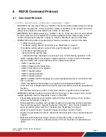
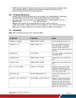
•   TERM is the termination character for the command. This can either be the ASCII carriage 

return character (0x0D), the ASCII line feed character (0x0A) or a semicolon. The 
response will use the same termination character. 

4.2  Protocol Encoding 

•   All parts of the command structure are case insensitive (e.g. “BRIGHTNESS”, “brightness” 

and BrIgHtNeSs” are all the same). Responses will always be in capital letters. 

•   Excessive white space is allowed (e.g. “BRIGHTNESS=50”, “BRIGHTNESS = 50” and 

“BRIGHTNESS                =                  50” are all the same). 

•   Modifiers and operands can be separated by commas, spaces or both (e.g. 

“GAIN=100,100,100”, “GAIN=100 100 100” and “GAIN=100, 100, 100” are all the same). 
Responses will always separate with one space between modifiers and operands). 

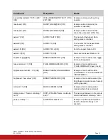
4.3  Examples 

Note: 

[CR] is the ASCII carriage return character (0x0D). 


Command 

Response 

Notes 

brightness = 100 [CR] 

BRIGHTNESS:100 [CR] 

Sets the Brightness value to 100 

brightness = 100; 

BRIGHTNESS:100; 

Also sets the Brightness value to 
100, but uses the ‘;’ termination 
character instead of [CR]. The 
response uses the same termination 
character. 

200=100 [CR] 

200:100 [CR] 

“200” is the numeric command code 
for “BRIGHTNESS” 

bri [CR] 

BRIGHTNESS:101 [CR] 

Increments the current Brightness 
value 

brightness- [CR] 

BRIGHTNESS:100 [CR] 

Decrements the current Brightness 
value 

gain = 101 102 103 [CR] 

GAIN:101 102 103 [CR] 

Example command with multiple 
operators (sets Red Gain to 101, 
Green Gain to 102 and Blue Gain to 
103, on the current zone) 

gain(current red)+ 

GAIN(CURRENT RED):102 

Increments the Red Gain on the 
current zone 

gain(zone.1, all) = 104,105,106 

GAIN(ZONE.1 ALL):104 105 106 

Example command with multiple 
modifiers, multiple operators and 
different separators between the 
modifiers and operators (sets Red 
Gain to 104, Green Gain to 105 and 
Blue Gain to 106, on Zone 1) 

Содержание UltraRes URX100

Страница 1: ...Page 1 Planar UltraRes X Series RS232 User Manual 020 1397 00B User Manual Planar UltraRes X Series RS232 URX75 URX75 ERO URX75 ERO T URX85 URX85 ERO URX85 ERO T URX100 URX100 ERO URX100 ERO T...

Страница 2: ...this manual the Company shall not be liable for errors or omissions contained herein or for incidental or consequential damages in connection with the furnishing performance or use of this material W...

Страница 3: ...Cable 5 4 RS232 Command Protocol 6 4 1 Command Structure 6 4 2 Protocol Encoding 7 4 3 Examples 7 5 RS232 Codes 9 5 1 Current Zone Layout 47 5 2 Key 48 5 3 Timezone 50 6 Sending Serial Commands via U...

Страница 4: ...ommunication can occur over RS232 USB B or LAN 1 Applicable Models This RS 232 user manual applies to all Planar UltraRes X Series models with the exception of the UR8450 and UR9850 models The RS232 i...

Страница 5: ...r UltraRes X Series RS232 User Manual 020 1397 00B Page 5 3 Connecting the RS232 Cable The Female DB9 connector is wired as a Straight Through serial connection Pin Signal 1 NC 2 Tx 3 Rx 4 NC 5 GND 6...

Страница 6: ...s are as follows ERR 1 Invalid syntax ERR 2 Reserved for future use ERR 3 Command not recognized ERR 4 Invalid modifier ERR 5 Invalid operands ERR 6 Invalid operator ACK indicates that the message is...

Страница 7: ...the ASCII carriage return character 0x0D Command Response Notes brightness 100 CR BRIGHTNESS 100 CR Sets the Brightness value to 100 brightness 100 BRIGHTNESS 100 Also sets the Brightness value to 100...

Страница 8: ...Also sets the Aspect Ratio to Fill brightness CR BRIGHTNESS ERR 1 CR Example of an invalid syntax isn t a valid operator fake command 1 CR FAKE COMMAND ERR 3 CR Example of an invalid opcode FAKE COMM...

Страница 9: ...ECT ZONE 1 AUTO In many instances a modifier may be omitted and the display will replace it with a default value For example the default modifier for the ASPECT command is CURRENT so the following two...

Страница 10: ...X 7 CYAN Y 8 MAGENTA X 9 MAGENTA Y 10 YELLOW X 11 YELLOW Y 12 WHITE X 13 WHITE Y None Set all 14 values at once 0 800 No Set REC709 red x color point in Zone 1 to 0 640 CMS ZONE 1 REC709 RED X 640 CM...

Страница 11: ...9 MAGENTA Y 10 YELLOW X 11 YELLOW Y 12 WHITE X 13 WHITE Y String No Zone 1 REC709 red x coordinate is achievable CMSFLAG ZONE 1 REC709 RED X CMSFLAG ZONE 1 REC709 RED X Zone 2 EBU blue y coordinate is...

Страница 12: ...5 DP No AUDIO INPUT AUDIO INPUT HDMI 1 Returns the input source in the zone currently playing audio as chosen by Audio Select Audio Select AUDIO ZONE 1007 Zone 0 ZONE 1 1 ZONE 2 2 ZONE 3 3 ZONE 4 No...

Страница 13: ...sity Balance AUDIO BALANCE 1000 0 100 No AUDIO BALANCE 50 AUDIO BALANCE 50 See Main Audio Balance Bass AUDIO BASS 1001 0 100 No AUDIO BASS 50 AUDIO BASS 50 See Main Audio Bass Blank Screen Color BLANK...

Страница 14: ...Code Operators Modifiers Operands Available in Standby Example Notes Color COLOR 202 Zone 0 ZONE 1 1 ZONE 2 2 ZONE 3 3 ZONE 4 253 ALL INPUT 254 ALL 254 ALL ZONE 255 CURRENT None CURRENT 0 100 No For Z...

Страница 15: ...O Reading the actual Color Gamut for the current zone COLOR GAMUT CURRENT ACTUAL COLORSPACE CURRENT ACTUAL RGB Copy the Zone 2 REC709 gamut to all zones COLOR GAMUT ZONE 2 COPY REC709 COLOR GAMUT ZONE...

Страница 16: ...pace for the current zone COLORSPACE CURRENT SETTING AUTO COLORSPACE CURRENT SETTING AUTO Reading the actual Color Space for the current zone COLORSPACE CURRENT ACTUAL COLORSPACE CURRENT ACTUAL RGB Se...

Страница 17: ...st Color Temperature Content Rotation ROTATE 504 Zone 0 ZONE 1 1 ZONE 2 2 ZONE 3 3 ZONE 4 253 ALL INPUT 254 ALL 254 ALL ZONE 255 CURRENT None CURRENT 0 NONE 90 90 180 180 270 270 No For Zone 1 ROTATE...

Страница 18: ...t CURRENT ZONE LAYOUT 108 0 S 1 1 P UL 1 2 P UL 2 3 P UR 1 4 P UR 2 5 P LL 1 6 P LL 2 7 P LR 1 8 P LR 2 9 D L 1 10 D L 2 11 D T 1 12 D T 2 13 T L 1 14 T L 2 15 T L 3 16 T R 1 17 T R 2 18 T R 3 19 T T...

Страница 19: ...207 0 OFF 1 ON Yes NETWORK DHCP ON NETWORK DHCP ON See Main Advanced Settings Network DHCP Diagnostic Color DIAGNOSTIC COLOR 206 Zone 0 ZONE 1 1 ZONE 2 2 ZONE 3 3 ZONE 4 253 ALL INPUT 254 ALL 254 ALL...

Страница 20: ...only None STATIC for writes only String Yes Read the current DNS server 1 value NETWORK DNS1 NETWORK DNS1 172 16 0 140 Write the DNS server 1 for static IP NETWORK DNS1 STATIC 8 8 8 8 NETWORK DNS1 ST...

Страница 21: ...gned Integer 3 4K60 2 4K30 1 1080P No Read the EDID type for HDMI 1 EDID TIMING HDMI 1 TYPE EDID TIMING HDMI 1 TYPE 4K60 Set the HDMI 2 EDID horizontal active to 3840 EDID TIMING HDMI 2 HACTIVE 3840 E...

Страница 22: ...E See Main Advanced Settings System Settings Enable Status LED Error Log ERROR LOG 2311 Log Entry Number 1 65535 No ERROR LOG 1 ERROR LOG 1 Wed Sep 16 13 39 33 2015 CRIT Power supply 2 issue Lists any...

Страница 23: ...Zone 0 ZONE 1 1 ZONE 2 2 ZONE 3 3 ZONE 4 253 ALL INPUT 254 ALL 254 ALL ZONE 255 CURRENT None CURRENT Mod 2 Color 0 RED 1 GREEN 2 BLUE 255 ALL None ALL For RED GREEN and BLUE modifiers one operand 0 20...

Страница 24: ...5 6 1 8 7 1 85 8 1 9 9 1 95 10 2 0 11 2 05 12 2 1 13 2 15 14 2 2 15 2 25 16 2 3 17 2 35 18 2 4 19 2 45 20 2 5 21 2 55 22 2 6 23 2 65 24 2 7 25 2 75 26 2 8 No For Zone 1 GAMMA ZONE 1 2 2 GAMMA ZONE 1 2...

Страница 25: ...sented in the specified zone includes HDR metadata Help HELP 2300 0 FIRST 2147483647 NEXT String Yes To get help on the OSD STATUS command HELP OSD STATUS HELP OSD STATUS Numeric Value 1308 Operators...

Страница 26: ...Display Invalid host name can t use spaces HOSTNAME My Display HOSTNAME ERR 5 Sets the network hostname for the display Default string is UltraRes Image Information SIGNAL INFO 300 Mod 1 Zone 0 ZONE 1...

Страница 27: ...10 20 For the X modifier see Main Image Adjust Image Position Move Horizontal For the Y modifier see Main Image Adjust Image Position Move Vertical IP Address IPV4 ADDRESS 1204 0 STATIC None Current...

Страница 28: ...T 7 TRIPLE L 8 TRIPLE R 9 TRIPLE T 10 TRIPLE B 11 TRIPLE M 12 QUAD No To change the Dual layout to top and bottom LAYOUT DUAL DUAL T LAYOUT DUAL DUAL T To change the PIP position to top left and immed...

Страница 29: ...ODEL SERIES UltraRes Always returns UltraRes for this product Other products using this protocol will have a different response for this command Multi Source View MULTI VIEW 102 0 SINGLE 1 DUAL 2 TRIP...

Страница 30: ...205 Zone 0 ZONE 1 1 ZONE 2 2 ZONE 3 3 ZONE 4 253 ALL INPUT 254 ALL 254 ALL ZONE 255 CURRENT None CURRENT 0 OFF 1 LOW 2 MEDIUM 3 HIGH No For Zone 1 NOISE REDUCTION ZONE 1 OFF NOISE REDUCTION ZONE 1 OFF...

Страница 31: ...one operand 0 100 For ALL operand three operands Red Offset 0 100 Green Offset 0 100 Blue Offset 0 100 No For red offset on Zone 1 OFFSET ZONE 1 RED 50 OFFSET ZONE 1 RED 50 For all three offsets on t...

Страница 32: ...ages OSD Rotation OSD Status OSD STATUS 1308 0 DISABLE 1 ENABLE No OSD STATUS OSD STATUS ENABLE Indicates whether the OSD menu message box or confirmation dialog is currently being shown on the displa...

Страница 33: ...MEDIUM 2 LARGE No PIP SIZE MEDIUM PIP SIZE MEDIUM See Main Inputs and Views Multi Source View Advanced Layouts PIP Size PIP Swap PIP SWAP 106 No PIP SWAP PIP SWAP ACK See IR remote control key PIP SWA...

Страница 34: ...used to program any delay value Power Saving Mode POWER SAVE MODE 1405 0 Disable 1 Power Down 2 Wake On Signal No POWER SAVE MODE Power Down Or POWER SAVE MODE 1 See Main Advanced Settings Power Power...

Страница 35: ...following command PRESET LIST FIRST Use the following command to read additional filled presets PRESET LIST NEXT Continue sending the second command above until the last number shown matches the valu...

Страница 36: ...eset 4 PRESET RECALL 4 PRESET RECALL 4 ACK See Main Presets Recall Preset Save PRESET SAVE 2002 Preset Number 1 1000 No Save to Preset 4 PRESET SAVE 4 PRESET SAVE 4 ACK See Main Presets Save A maximum...

Страница 37: ...SAVE DIAGNOSTICS USB SAVE DIAGNOSTICS USB ACK See Main Advanced Settings System Settings Save Diagnostics to USB Schedule SCHEDULE 2100 Mod 1 Slot 1 20 Mod 2 Parameter 0 FREQ 1 MINUTE 2 HOUR 3 DAY 4 A...

Страница 38: ...e string used for the schedule slots in the Main Advanced Settings Schedule menu Schedule Frequency SCHEDULE FREQUENCY 2103 Slot 1 20 0 DAILY 1 WEEKLY 2 WEEKDAYS 3 WEEKENDS Yes Change the frequency fo...

Страница 39: ...MD5 6 LOGIN 7 NTLM Yes NETWORK SMTP AUTHENTICATI ON AUTO NETWORK SMTP AUTHENTICATI ON AUTO See Remote Monitoring Software Notifications Authentication SMTP Connec tion Encryption NETWORK SMTP ENCRYPTI...

Страница 40: ...Notifications User Name SNMP SNMP ENABLE 1231 0 On 1 Off No SNMP ENABLE ON Used to enable or disable SNMP support Source Message SOURCE MESSAGE 111 Zone 0 ZONE 1 1 ZONE 2 2 ZONE 3 3 ZONE 4 255 CURRENT...

Страница 41: ...SCREEN ENABLE SPLASH SCREEN ENABLE See Main Advanced Settings Menus and Messages Allow Splash Screen Subnet Mask IPV4 NETMASK 1205 0 STATIC None Current for reads only None STATIC for writes only Str...

Страница 42: ...t power mode Not all functions are available POWERING ON The system is transitioning from the STANDBY state to the ON state ON The system is on with the backlight on POWERING DOWN The system is transi...

Страница 43: ...11 GRAYBAR 12 REDBAR 13 GREENBAR 14 BLUEBAR 16 CHECKER BOARD 18 COLORBAR No PATTERN GRAYBAR PATTERN GRAYBAR ACK See Main Advanced Settings Test Pattern Time TIME 1100 0 YEAR 1 MONTH 2 DATE 3 HOUR 4 M...

Страница 44: ...Time Month Time String TIME STRING 1103 String Yes TIME STRING TIME STRING 2015 09 01 13 21 See Main Advanced Settings Schedule Date Time Time Zone TIMEZONE 1208 See separate table Yes TIMEZONE UTCM0...

Страница 45: ...No AUDIO TREBLE 50 AUDIO TREBLE 50 See Main Audio Treble Use Network Time NETWORK NTP 1209 0 OFF 1 ON Yes NETWORK NTP ON NETWORK NTP ON See Main Advanced Settings Schedule Set Date and Time Use Networ...

Страница 46: ...Available in Standby Example Notes Wall WALL 503 0 ENABLE 1 WIDTH 2 HEIGHT 3 COLUMN 4 ROW 5 FRAME ENABLE 6 FRAME WIDTH 7 FRAME HEIGHT 0 100 No Set the wall width to 4 WALL WIDTH 4 WALL WIDTH 4 See Ma...

Страница 47: ...ew One Left Two Right Zone 1 14 T L 2 Triple View One Left Two Right Zone 2 15 T L 3 Triple View One Left Two Right Zone 3 16 T R 1 Triple View Two Left One Right Zone 1 17 T R 2 Triple View Two Left...

Страница 48: ...GHT Navigate right 17 KEY 1 1 Number button 1 18 KEY 2 2 Number button 2 19 KEY 3 3 Number button 3 20 KEY 4 4 Number button 4 21 KEY 5 5 Number button 5 22 KEY 6 6 Number button 6 23 KEY 7 7 Number b...

Страница 49: ...setting 271 PIP SWAP PIP SWAP Swaps the main and PIP windows 272 HDMI1 HDMI 1 Selects HDMI 1 for the current zone 273 HDMI2 HDMI 2 Selects HDMI 2 for the current zone 274 HDMI3 HDMI 3 Selects HDMI 3 f...

Страница 50: ...CM0600 CENTRAL AMERICA UTC 06 00 Central America 10 UTCM0600 CENTRAL TIME US CANADA UTC 06 00 Central Time US and Canada 11 UTCM0600 GUADALAJARA MEXICO CITY MONTERREY UTC 06 00 Guadalajara Mexico City...

Страница 51: ...sal Time 35 UTC DUBLIN EDINBURGH LISBON LONDON UTC Dublin Edinburgh Lisbon London 36 UTC MONROVIA REYKJAVIK UTC Monrovia Reykjavik 37 UTCP0100 AMSTERDAM BERLIN BERN ROME STOCKHOLM VIENNA UTC 01 00 Ams...

Страница 52: ...PETERSBURG VOLGOGRAD RTZ 2 UTC 03 00 Moscow St Petersburg Volgograd RTZ 2 58 UTCP0300 NAIROBI UTC 03 00 Nairobi 59 UTCP0330 TEHRAN UTC 03 30 Tehran 60 UTCP0400 ABU DHABI MUSCAT UTC 04 00 Abu Dhabi Mus...

Страница 53: ...81 UTCP0800 KUALA LUMPUR SINGAPORE UTC 08 00 Kuala Lumpur Singapore 82 UTCP0800 PERTH UTC 08 00 Perth 83 UTCP0800 TAIPEI UTC 08 00 Taipei 84 UTCP0800 ULAANBAATAR UTC 08 00 Ulaanbaatar 85 UTCP0900 OSA...

Страница 54: ...LOVSK KAMCHATSKY RTZ 11 UTC 12 00 Anadyr Petropavlovsk Kamchatsky RTZ 11 99 UTCP1200 AUCKLAND WELLINGTON UTC 12 00 Auckland Wellington 100 UTCP1200 COORDINATED UNIVERSAL TIMEP12 UTC 12 00 Coordinated...

Страница 55: ...s section if you have already installed the USB drivers on your computer Automatically installing the USB drivers In most cases the USB driver installation can be performed using the automated driver...

Страница 56: ...r UltraRes X Series RS232 User Manual 020 1397 00B Page 56 2 The USB drivers will be automatically installed 3 When the installation completes click Finish The USB driver installation process is now c...

Страница 57: ...n the USB cable to your computer and to the Planar UltraRes X Series panel 2 Windows will detect the new hardware and attempt to install the drivers on its own If you do not see the Installing device...

Страница 58: ...nar UltraRes X Series RS232 User Manual 020 1397 00B Page 58 5 Open the Start menu and select Control Panel 6 Select Hardware and Sound In the following menu under Devices and Printers select Device M...

Страница 59: ...Manager there will be a Planar UltraRes item in the Other Devices section Right click on Planar UltraRes and select Update Driver Software 8 Follow the steps defined in the Update Driver Software wiza...

Страница 60: ...USB drivers are included on the USB flash drive in the accessory kit they can also be obtained from http www planar com support Use the Browse button to locate the directory where the USB drivers are...

Страница 61: ...process is now complete 6 2 Using the Planar UltraRes X Series USB Connection Once the USB drivers are installed the PC will recognize the USB B connection as a regular serial port The USB B connectio...

Страница 62: ...set as RS232 It is convenient for IP control applications and can be tested with a TCP terminal program such as Tera Term or a UDP terminal program such as Hercules Notice the following in the TCP ex...

Страница 63: ...UDP example below using Hercules The IP address is 10 15 0 67 Port 57 is selected 444953504C41592E504F5745523D310D in the Send box is hex for DISPLAY POWER 1 Note Most UDP terminal programs won t auto...

Отзывы: