background image

Page 7

For technical questions, please call 1-800-444-3353.

Item 69887 


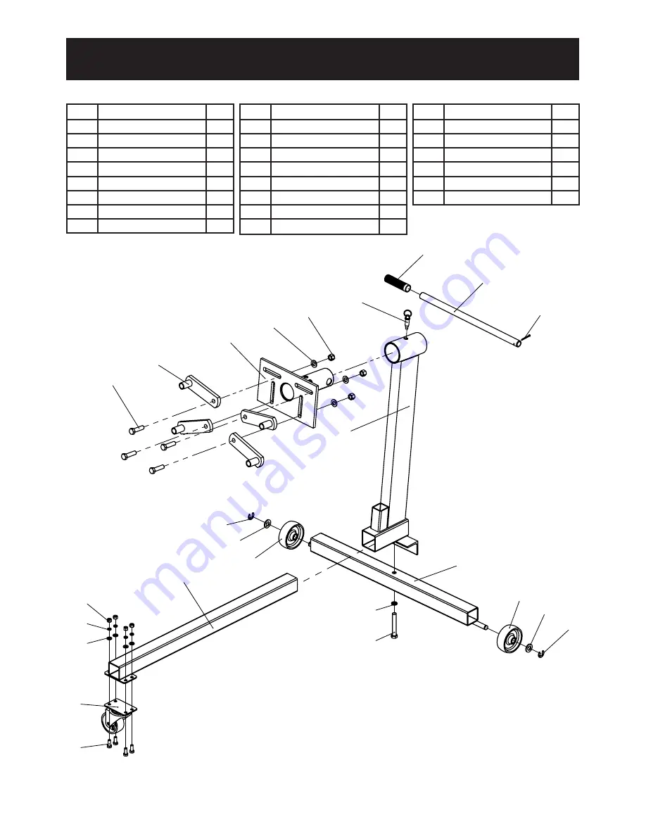
Parts List and Diagram

3

2

1

4

5

21

20

13

12

11

22

13

11

12

14

15
16
17

18

19

9

10

8

6

7

Part Description

Qty

1

Split Pin

1

2

Handle

1

3

Handle Grip

1

4

Pin

1

5

Post

1

6

Nut M12

4

7

Washer Ø12

4

8

Mounting Plate

1

Part Description

Qty

9

Mounting Arm

4

10

Bolt M12x45

4

11

Snap Ring Ø14

2

12

Washer Ø14

2

13

Rear Wheels

2

14

Middle Beam

1

15

Nut M8

4

16

Spring Washer Ø8

4

Part Description

Qty

17

Washer Ø8

4

18

3" Caster

1

19

Bolt M8x20

4

20

Bolt M12x80

1

21

Spring Washer Ø12 1

22

Rear Beam

1

Содержание 69887

Страница 1: ......

Страница 2: ...these instructions may result in personal injury and or property damage 1 Study understand and follow all instructions before operating this device 2 Do not exceed rated capacity Be aware of dynamic loading Sudden load movement may briefly create excess load causing product failure 3 Use only on hard level surfaces 4 Lock mounting plate rotating mechanism before applying a load 5 Assure load is ce...

Страница 3: ...to Middle Beam 1 Insert Middle Beam 14 into the receiver at the base of the Post 5 Align hole in Rear Beam 22 with hole at base of Post and attach with Bolt 20 and Spring Washer 21 as shown Caster 18 Axle Wheel 13 Washer 12 Snap Ring 11 Nut 15 Spring Washer 16 Washer 17 Bolt 19 Middle Beam 14 Figure B Attach Wheels and Casters 2 Attach Caster 18 to the Middle Beam 14 using one Bolt 19 Washer 17 Sp...

Страница 4: ...Slide Handle Grip 3 on to Handle 2 6 Insert the Handle 2 through the Mounting Plate 8 shaft and secure with Split Pin 1 Pin 4 Bolt 10 Washer 7 Nut 6 Mounting Arm 9 Figure D Install Mounting Arms and Lock Rotation 7 Attach the Mounting Arms 9 to the slots in the Mounting Plate 8 using the Bolts 10 Washers 7 and Nuts 6 8 To lock Mounting Plate 8 rotation align a hole on it with the hole on the top o...

Страница 5: ...4 Tighten the Bolts 10 and Nuts 6 that hold the Mounting Arms 9 to the Mounting Plate 8 securely 5 Slowly lower the hoist engine crane sold separately until all the engine s weight is held by the stand 6 Safely release the engine from the hoist engine crane 7 Slowly rotate the engine to the desired angle and insert the Pin 4 into the top of the Post 5 Rotating Engine TO PREVENT SERIOUS INJURY Be p...

Страница 6: ...ith a clean moist cloth PLEASE READ THE FOLLOWING CAREFULLY THE MANUFACTURER AND OR DISTRIBUTOR HAS PROVIDED THE PARTS LIST AND ASSEMBLY DIAGRAM IN THIS DOCUMENT AS A REFERENCE TOOL ONLY NEITHER THE MANUFACTURER OR DISTRIBUTOR MAKES ANY REPRESENTATION OR WARRANTY OF ANY KIND TO THE BUYER THAT HE OR SHE IS QUALIFIED TO MAKE ANY REPAIRS TO THE PRODUCT OR THAT HE OR SHE IS QUALIFIED TO REPLACE ANY PA...

Страница 7: ... Split Pin 1 2 Handle 1 3 Handle Grip 1 4 Pin 1 5 Post 1 6 Nut M12 4 7 Washer Ø12 4 8 Mounting Plate 1 Part Description Qty 9 Mounting Arm 4 10 Bolt M12x45 4 11 Snap Ring Ø14 2 12 Washer Ø14 2 13 Rear Wheels 2 14 Middle Beam 1 15 Nut M8 4 16 Spring Washer Ø8 4 Part Description Qty 17 Washer Ø8 4 18 3 Caster 1 19 Bolt M8x20 4 20 Bolt M12x80 1 21 Spring Washer Ø12 1 22 Rear Beam 1 ...

Страница 8: ... so the above limitation of exclusion may not apply to you THIS WARRANTY IS EXPRESSLY IN LIEU OF ALL OTHER WARRANTIES EXPRESS OR IMPLIED INCLUDING THE WARRANTIES OF MERCHANTABILITY AND FITNESS To take advantage of this warranty the product or part must be returned to us with transportation charges prepaid Proof of purchase date and an explanation of the complaint must accompany the merchandise If ...

Отзывы: