to manually overcome system malfunctions or to meet special pilot needs such as a deliberate wheels up landing
needed for emergency landings on water, or during various flight maneuvers where airspeed and power settings
would normally allow the gear to extend. It also permits gear retraction after takeoff at speeds lower than those
normally permitted by the automatic system. When using the manual extension lever, the gear position is
controlled by the selector switch, regardless of airspeed/power combinations. An override latch mechanism is
installed which allows the pilot to latch the extension lever in the up override position, thus bypassing the
automatic portion of the system on airplanes that have operational back-up gear extender systems. A flashing
warning light is mounted below the gear selector lever to indicate whenever the latch is in use. The latch is
disengaged by pulling up on the extension lever. To assist the nose gear to extend under these conditions are two
springs, one inside the other, mounted on arms above the gear links. The main gears require no assist springs.
Once the gears are down and the downlock hooks engage, a spring maintains each hook in the locked position
until hydraulic pressure again releases it. A further description of the hydraulic system and the gear back-up
extender unit may be found in Section VI, Hydraulic System.
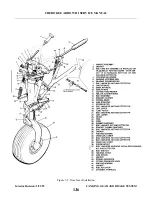
The nose gear is steerable through a 60 degree arc by the use of the rudder pedals. As the gear retracts,
h o w e v e r, the steering linkage becomes separated from the gear so that rudder pedal action with the gear retracted
is not impeded by the nose gear operation. A shimmy dampener is also incorporated in the nose wheel steering
mechanism. Bungee springs are also incorporated on the push rods. These springs make lighter and smoother
ground steering possible.
The two main wheels are equipped with self-adjusting single disc hydraulic brake assemblies. Toe brakes are
standard on both the pilot’s and copilot’s rudder pedals. A parking brake is incorporated with the handle, and may
be used by pulling back on the handle and pushing forward on the button to the left of the handle. To release the
hand brake, pull aft on the handle and allow it to swing forward. Hydraulic fluid for the cylinders is supplied by a
reservoir installed on the left forward side of the firewall.
WA R N I N G
Place airplane on jacks prior to troubleshooting landing gear system.
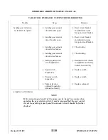
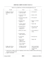
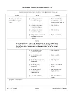
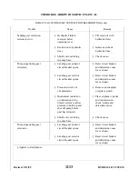
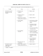
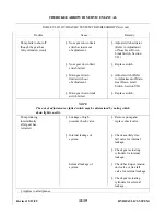
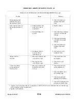
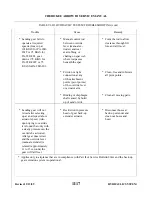
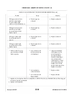
7-3. TROUBLESHOOTING. Mechanical and electrical switch troubles peculiar to the landing gear system are
listed in Table VII-II at the back of this section. When troubleshooting, first eliminate hydraulic malfunctions as
listed in Section VI. Then proceed to switch malfunctions and last to the mechanical operation of the gear itself,
both of which are listed in this section. Always place the airplane on jacks before attempting any troubleshooting
of the gear. To operate the gear, the emergency gear lever must be maintained in the up override position.
7-4. LANDING GEAR SYSTEM.
7-5. NOSE LANDING GEAR.
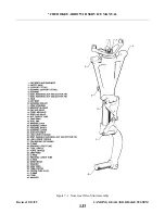
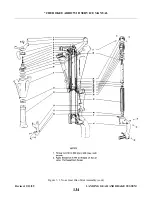
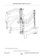
7-6. DISASSEMBLY OF NOSE GEAR OLEO. (Refer to Figure 7-1.) The nose gear oleo assembly may be
removed and disassembled from the gear oleo housing with the gear removed from or installed on the airplane.
a .
Place the airplane on jacks. (Refer to Jacking, Section II.)
b . Place a drip pan under the nose gear to catch spillage.
c .
Remove air and fluid from the oleo strut. Depress the air valve core pin until strut chamber pressure has
diminished, remove the filler plug and with a small hose siphon as much hydraulic fluid from the strut as
p o s s i b l e .
top of the unit and remove cap bolts (1) that attach steering arm (11) and aligner guide bracket (12) to the
top of the oleo cylinder (23).
e .
Disconnect the shimmy dampener by removing each cotter pin, nut, washer and bolt that connects the
dampener to the oleo cylinder (23) and housing.
f .
Release and remove the snap ring (17) and washer(s) (43), if installed, at the top of the housing (21), and
pull the complete cylinder and fork assembly from the bottom of the housing. The upper and lower
housing bushings (20 and 22) should remain pressed in the housing.
Revised: 2/13/89
1J1
* CHEROKEE ARROW III SERVICE MANUAL
LANDING GEAR AND BRAKE SYSTEM
Содержание ARROW III
Страница 4: ...THIS PAGE INTENTIONALLY LEFT BLANK 1A4...
Страница 12: ...THIS PAGE INTENTIONALLY LEFT BLANK 1A12...
Страница 93: ...Figure 4 1 Aileron and Flap Installation Issued 12 15 76 1D21 CHEROKEE ARROW III SERVICE MANUAL STRUCTURES...
Страница 94: ...Figure 4 2 Wing Installation Revised 2 13 89 1D22 CHEROKEE ARROW III SERVICE MANUAL STRUCTURES...
Страница 95: ...Figure 4 2 Wing Installation cont Revised 11 21 80 1D23 CHEROKEE ARROW III SERVICE MANUAL STRUCTURES...
Страница 101: ...Figure 4 4 Empennage Group Installation Revised 11 21 80 1E5 CHEROKEE ARROW III SERVICE MANUAL STRUCTURES...
Страница 102: ...Figure 4 4 Empennage Group Installation cont Revised 11 21 80 1E6 CHEROKEE ARROW III SERVICE MANUAL STRUCTURES...
Страница 104: ...Figure 4 5 Windshield Installation Typical Issued 12 15 76 1E8 CHEROKEE ARROW III SERVICE MANUAL STRUCTURES...
Страница 107: ...Figure 4 7 Skin Materials and Thickness Issued 12 15 76 1E11 CHEROKEE ARROW III SERVICE MANUAL STRUCTURES...
Страница 117: ...Figure 4 9 Control Surface Balance Tool Issued 12 15 76 1E21 CHEROKEE ARROW III SERVICE MANUAL STRUCTURES...
Страница 124: ...Figure 4 15 Identification of Aircraft Fluid Lines Added 5 1 80 1F4 CHEROKEE ARROW III SERVICE MANUAL STRUCTURES...
Страница 130: ...TABLE V ll CABLE TENSION VS AMBIENT TEMPERATURE Revised 2 13 89 1F10 CHEROKEE ARROW III SERVICE MANUAL SURFACE CONTROLS...
Страница 131: ...Figure 5 1 Control Column Assembly Revised 5 1 80 1F11 CHEROKEE ARROW III SERVICE MANUAL SURFACE CONTROLS...
Страница 132: ...Figure 5 la Method of Installing Rod End Bearings Added 12 11 78 1F12 CHEROKEE ARROW III SERVICE MANUAL SURFACE CONTROLS...
Страница 135: ...Figure 5 2 Aileron Controls Revised 11 21 80 1F15 CHEROKEE ARROW III SERVICE MANUAL SURFACE CONTROLS...
Страница 142: ...Figure 5 6 Stabilator Controls Revised 5 1 80 1F22 CHEROKEE ARROW III SERVICE MANUAL SURFACE CONTROLS...
Страница 147: ...Figure 5 8 Stabilator Trim Control Issued 12 15 76 1G3 CHEROKEE ARROW III SERVICE MANUAL SURFACE CONTROLS...
Страница 149: ...Figure 5 9 Rudder and Steering Pedal Assembly Issued 12 15 76 1G5 CHEROKEE ARROW III SERVICE MANUAL SURFACE CONTROLS...
Страница 151: ...Figure 5 10 Rudder Controls Revised 12 11 78 1G7 CHEROKEE ARROW III SERVICE MANUAL SURFACE CONTROLS...
Страница 157: ...Figure 5 15 Flap Controls Interim Revision 2 21 95 1G13 CHEROKEE ARROW III SERVICE MANUAL SURFACE CONTROLS...
Страница 162: ...Figure 5 20 Fabricated Stabilator Rigging Tool Issued 12 15 76 1G18 CHEROKEE ARROW III SERVICE MANUAL SURFACE CONTROLS...
Страница 163: ...Figure 5 21 Fabricated Rudder Rigging Tool Issued 12 15 76 1G19 CHEROKEE ARROW III SERVICE MANUAL SURFACE CONTROLS...
Страница 171: ...lH3 INTENTIONALLY LEFT BLANK...
Страница 172: ...lH4 INTENTIONALLY LEFT BLANK...
Страница 178: ...Figure 6 2 Hydraulic System Installation Revised 2 13 89 1H10 CHEROKEE ARROW III SERVICE MANUAL HYDRAULIC SYSTEM...
Страница 188: ...THIS PAGE INTENTIONALLY LEFT BLANK Revised 2 13 89 1H20 CHEROKEE ARROW III SERVICE MANUAL HYDRAULIC SYSTEM...
Страница 190: ...Figure 6 6 Gear Back up Extender Actuator Revised 2 13 89 1H22 CHEROKEE ARROW III SERVICE MANUAL HYDRAULIC SYSTEM...
Страница 195: ...Figure 6 7 Nose Gear Actuating Cylinder Revised 2 13 89 1I3 CHEROKEE ARROW III SERVICE MANUAL HYDRAULIC SYSTEM...
Страница 198: ...Figure 6 9 Main Gear Actuating Cylinder Revised 2 13 89 1I6 CHEROKEE ARROW III SERVICE MANUAL HYDRAULIC SYSTEM...
Страница 212: ...GRIDS lI20 AND lI21 INTENTIONALLY LEFT BLANK Revised 2 13 89 1I20 CHEROKEE ARROW III SERVICE MANUAL HYDRAULIC SYSTEM...
Страница 234: ...Figure 7 11 Aligning Main Gear Revised 2 13 89 1J19 CHEROKEE ARROW III SERVICE MANUAL LANDING GEAR AND BRAKE SYSTEM...
Страница 254: ...Figure 7 19 Removal of Anchor Bolt Revised 2 13 89 1K15 CHEROKEE ARROW III SERVICE MANUAL LANDING GEAR AND BRAKE SYSTEM...
Страница 259: ...Figure 7 23 Toe Brake Installation Revised 2 13 89 1K20 CHEROKEE ARROW III SERVICE MANUAL LANDING GEAR AND BRAKE SYSTEM...
Страница 264: ...Figure 7 26 Bleeding Brakes Revised 2 13 89 1L1 CHEROKEE ARROW III SERVICE MANUAL LANDING GEAR AND BRAKE SYSTEM...
Страница 286: ...THIS PAGE INTENTIONALLY LEFT BLANK Revised 2 13 89 2A8...
Страница 292: ...Figure 8 3 Propeller Installation Revised 8 31 77 2A14 CHEROKEE ARROW III SERVICE MANUAL POWER PLANT CONTINENTAL...
Страница 298: ...Figure 8 6 Engine Installation Revised 12 11 78 2A20 CHEROKEE ARROW III SERVICE MANUAL POWER PLANT CONTINENTAL...
Страница 323: ...Figure 8 28 Ignition Schematic Revised 8 31 77 2B21 CHEROKEE ARROW III SERVICE MANUAL POWER PLANT CONTINENTAL...
Страница 330: ...Figure 8 33 Engine Controls Revised 8 31 77 2C4 CHEROKEE ARROW III SERVICE MANUAL POWER PLANT CONTINENTAL...
Страница 347: ...Figure 8A 1 Propeller Installation Hartzell Revised 5 1 80 2C21 CHEROKEE ARROW III SERVICE MANUAL POWER PLANT LYCOMING...
Страница 354: ...Figure 8A4 Engine Installation PA 28R 201 Revised 10 18 83 2D4 CHEROKEE ARROW III SERVICE MANUAL POWER PLANT LYCOMING...
Страница 385: ...Figure 9 1 Fuel System Diagram PA 28R 201 Issued 12 15 76 2E11 CHEROKEE ARROW III SERVICE MANUAL FUEL SYSTEM...
Страница 387: ...Figure 9 2 Fuel System Diagram PA 28R 201T Revised 2 13 89 2E13 CHEROKEE ARROW III SERVICE MANUAL FUEL SYSTEM...
Страница 389: ...Figure 9 3 Fuel Sender Units Installation Revised 2 13 89 2E15 CHEROKEE ARROW III SERVICE MANUAL FUEL SYSTEM...
Страница 409: ...Figure 10 1 Instrument Panel Typical Revised 2 13 89 2F11 CHEROKEE ARROW III SERVICE MANUAL INSTRUMENTS...
Страница 412: ...Figure 10 2 Pitot Static System Revised 2 13 89 2F14 CHEROKEE ARROW III SERVICE MANUAL INSTRUMENTS...
Страница 414: ...Figure 10 3 Vacuum Auxiliary Vacuum Installation Revised 2 13 89 2F16 CHEROKEE ARROW III SERVICE MANUAL INSTRUMENTS...
Страница 482: ...Figure 11 44b Ignition Switch Revised 2 13 89 2I12 CHEROKEE ARROW III SERVICE MANUAL ELECTRICAL SYSTEM...
Страница 483: ...Figure 11 45 Terminal Block Revised 2 13 89 2I13 CHEROKEE ARROW III SERVICE MANUAL ELECTRICAL SYSTEM...
Страница 498: ...TABLE XI VI ELECTRICAL SYMBOLS Revised 2 13 89 2J4 CHEROKEE ARROW III SERVICE MANUAL ELECTRICAL SYSTEM...
Страница 506: ...Figure 11 62 Instrument Lights PA 28R 201T Revised 2 13 89 2J12 CHEROKEE ARROW III SERVICE MANUAL ELECTRICAL SYSTEM...
Страница 507: ...Figure 11 63 Alternator and Starter PA 28R 201 Revised 2 13 89 2J13 CHEROKEE ARROW III SERVICE MANUAL ELECTRICAL SYSTEM...
Страница 510: ...Figure 11 65 Fuel Pump PA 28R 201T Revised 2 13 89 2J16 CHEROKEE ARROW III SERVICE MANUAL ELECTRICAL SYSTEM...
Страница 511: ...Figure 11 66 Landing Gear PA 28R 201 201T Revised 2 13 89 2J17 CHEROKEE ARROW III SERVICE MANUAL ELECTRICAL SYSTEM...
Страница 528: ...INTENTIONALLY LEFT BLANK 2K10 THRU 2L24 2K10...
Страница 542: ...Figure 14 4 Manifold Set Operation Revised 2 13 89 3A14 CHEROKEE ARROW III SERVICE MANUAL ACCESSORIES AND UTILITIES...
Страница 578: ...Figure 14 16 Fixed Oxygen System Revised 2 13 89 3C2 CHEROKEE ARROW III SERVICE MANUAL ACCESSORIES AND UTILITIES...
Страница 580: ...Figure 14 18 Oxygen Tubing Installation Revised 2 13 89 3C4 CHEROKEE ARROW III SERVICE MANUAL ACCESSORIES AND UTILITIES...
Страница 594: ...INTENTIONALLY LEFT BLANK 3C18 THRU 3L24...

