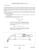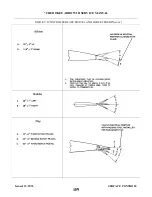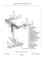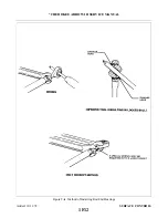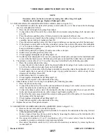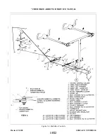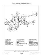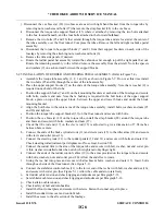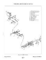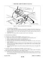
5-12. RIGGING AND ADJUSTMENT OF AILERON CONTROLS. (Refer to Figures 5-3 thru 5-4.)
NOTE
Flap adjustment must be complete before starting aileron adjustment.
a.
To check and adjust the rigging of the aileron controls, first set the right and left aileron bellcranks at
neutral position. (Ascertain that the control chains have been rigged per Paragraph 5-6.) This may be
accomplished by the following procedure:
l.
Place tee bar in full forward position, and maintain it in this position by use of a suitable tool or
by placing weights on the aft side of the stabilator if the stabilator cables have been previously
tensioned.
2. Remove the access plate to each aileron bellcrank located on the underside of the wing, forward of
the inboard end of the aileron by removing the plate attaching screws.
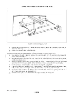
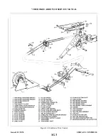
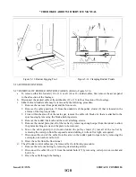
3. Affix a bellcrank rigging tool, as shown in Figure 5-3, between the forward arm of each bellcrank
and the adjacent outboard rib. (This tool may be fabricated from dimensions given in Figure 5-18.)
The slotted end of the tool fits on the arm forward of and adjacent to the primary control cable
end. The other end of the tool is positioned so that the side of the tool contacts the aft side of the
bellcrank stop. The bellcrank must be moved to allow a snug fit of the tool between the bellcrank
arm and rib. To do so, it may be necessary to loosen a primary control cable or the balance cable.
Neutral position of the bellcranks may also be found by locating the position at which the forward
and aft cable connection holes are an equal distance from the adjacent outboard wing rib.
b. With each bellcrank set at neutral, the ailerons may be checked and adjusted for neutral as follows:
1. Ascertain that the bellcrank rigging tool fits snug between the bellcrank and the rib.
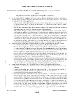
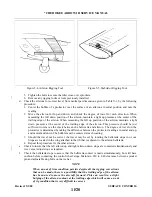
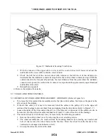
2. Place an aileron rigging tool as shown in Figure 5-4 against the underside of the wing and aileron
as close as possible to the inboard end of the aileron without contacting any rivets. The tool must
be positioned parallel with the wing ribs, with the aft end of the tool even with the trailing edge of
the aileron. (This tool may be fabricated from dimensions given in Figure 5-19.)
3. With the aileron control rod connected between the bellcrank and aileron, check that the surface of
the wing contacts the tool at its forward surface and at the spacer, and the trailing edge of the flap
contacts the aft end of the tool. The aileron is neutral at this position.
4. Should the three points not contact; loosen the jam nut at the aft end of the control rod and rotate
the rod until the three points contact. Apply a slight up pressure against the trailing edge of the
aileron while making this adjustment. The aileron may be allowed to “droop” by approximately
1/8’’ of an inch at the inboard trailing edge. After adjustment, retighten the jam nut.
c.
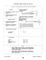
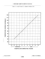
Adjust primary and balance cable tension as given in Table V-l by the following procedure:
1. Remove the two front seats, if desired, and the rear seat floor panel to facilitate in the necessary
operation.
2. Loosen the connecting bolts of the idler cross-over sprockets at the control tee bar to allow the
chain to fit snug around the control wheel sprockets and over the idler sprockets.
3. Ascertain that both bellcranks are at neutral position.
4. Adjust the turnbuckles, located in the access opening just aft of the main spar, of the primary and
balance cables to their proper cable tension and maintain neutral-center position of the control
wheels. Primary cable tension will be slightly less than balance cable tension, but still should be
within the tension specified. Adjust the cables so that the inboard end of the ailerons visually lines
up with the outboard end of the flap when a slight up pressure is applied to the middle of the
aileron to take the slack out of the hinge and linkage. To obtain neutral position of both control
wheels, it may also be necessary to adjust the roller chain turnbuckle located between the control
wheel sprockets. During adjustment, obtain a little more tension oh the primary control cables to
hold the bellcranks in neutral against the rigging tools, finishing with even tension on all cables.
Revised: 5/1/80
1F19
* CHEROKEE ARROW III SERVICE MANUAL
SURFACE CONTROLS
Содержание ARROW III
Страница 4: ...THIS PAGE INTENTIONALLY LEFT BLANK 1A4...
Страница 12: ...THIS PAGE INTENTIONALLY LEFT BLANK 1A12...
Страница 93: ...Figure 4 1 Aileron and Flap Installation Issued 12 15 76 1D21 CHEROKEE ARROW III SERVICE MANUAL STRUCTURES...
Страница 94: ...Figure 4 2 Wing Installation Revised 2 13 89 1D22 CHEROKEE ARROW III SERVICE MANUAL STRUCTURES...
Страница 95: ...Figure 4 2 Wing Installation cont Revised 11 21 80 1D23 CHEROKEE ARROW III SERVICE MANUAL STRUCTURES...
Страница 101: ...Figure 4 4 Empennage Group Installation Revised 11 21 80 1E5 CHEROKEE ARROW III SERVICE MANUAL STRUCTURES...
Страница 102: ...Figure 4 4 Empennage Group Installation cont Revised 11 21 80 1E6 CHEROKEE ARROW III SERVICE MANUAL STRUCTURES...
Страница 104: ...Figure 4 5 Windshield Installation Typical Issued 12 15 76 1E8 CHEROKEE ARROW III SERVICE MANUAL STRUCTURES...
Страница 107: ...Figure 4 7 Skin Materials and Thickness Issued 12 15 76 1E11 CHEROKEE ARROW III SERVICE MANUAL STRUCTURES...
Страница 117: ...Figure 4 9 Control Surface Balance Tool Issued 12 15 76 1E21 CHEROKEE ARROW III SERVICE MANUAL STRUCTURES...
Страница 124: ...Figure 4 15 Identification of Aircraft Fluid Lines Added 5 1 80 1F4 CHEROKEE ARROW III SERVICE MANUAL STRUCTURES...
Страница 130: ...TABLE V ll CABLE TENSION VS AMBIENT TEMPERATURE Revised 2 13 89 1F10 CHEROKEE ARROW III SERVICE MANUAL SURFACE CONTROLS...
Страница 131: ...Figure 5 1 Control Column Assembly Revised 5 1 80 1F11 CHEROKEE ARROW III SERVICE MANUAL SURFACE CONTROLS...
Страница 132: ...Figure 5 la Method of Installing Rod End Bearings Added 12 11 78 1F12 CHEROKEE ARROW III SERVICE MANUAL SURFACE CONTROLS...
Страница 135: ...Figure 5 2 Aileron Controls Revised 11 21 80 1F15 CHEROKEE ARROW III SERVICE MANUAL SURFACE CONTROLS...
Страница 142: ...Figure 5 6 Stabilator Controls Revised 5 1 80 1F22 CHEROKEE ARROW III SERVICE MANUAL SURFACE CONTROLS...
Страница 147: ...Figure 5 8 Stabilator Trim Control Issued 12 15 76 1G3 CHEROKEE ARROW III SERVICE MANUAL SURFACE CONTROLS...
Страница 149: ...Figure 5 9 Rudder and Steering Pedal Assembly Issued 12 15 76 1G5 CHEROKEE ARROW III SERVICE MANUAL SURFACE CONTROLS...
Страница 151: ...Figure 5 10 Rudder Controls Revised 12 11 78 1G7 CHEROKEE ARROW III SERVICE MANUAL SURFACE CONTROLS...
Страница 157: ...Figure 5 15 Flap Controls Interim Revision 2 21 95 1G13 CHEROKEE ARROW III SERVICE MANUAL SURFACE CONTROLS...
Страница 162: ...Figure 5 20 Fabricated Stabilator Rigging Tool Issued 12 15 76 1G18 CHEROKEE ARROW III SERVICE MANUAL SURFACE CONTROLS...
Страница 163: ...Figure 5 21 Fabricated Rudder Rigging Tool Issued 12 15 76 1G19 CHEROKEE ARROW III SERVICE MANUAL SURFACE CONTROLS...
Страница 171: ...lH3 INTENTIONALLY LEFT BLANK...
Страница 172: ...lH4 INTENTIONALLY LEFT BLANK...
Страница 178: ...Figure 6 2 Hydraulic System Installation Revised 2 13 89 1H10 CHEROKEE ARROW III SERVICE MANUAL HYDRAULIC SYSTEM...
Страница 188: ...THIS PAGE INTENTIONALLY LEFT BLANK Revised 2 13 89 1H20 CHEROKEE ARROW III SERVICE MANUAL HYDRAULIC SYSTEM...
Страница 190: ...Figure 6 6 Gear Back up Extender Actuator Revised 2 13 89 1H22 CHEROKEE ARROW III SERVICE MANUAL HYDRAULIC SYSTEM...
Страница 195: ...Figure 6 7 Nose Gear Actuating Cylinder Revised 2 13 89 1I3 CHEROKEE ARROW III SERVICE MANUAL HYDRAULIC SYSTEM...
Страница 198: ...Figure 6 9 Main Gear Actuating Cylinder Revised 2 13 89 1I6 CHEROKEE ARROW III SERVICE MANUAL HYDRAULIC SYSTEM...
Страница 212: ...GRIDS lI20 AND lI21 INTENTIONALLY LEFT BLANK Revised 2 13 89 1I20 CHEROKEE ARROW III SERVICE MANUAL HYDRAULIC SYSTEM...
Страница 234: ...Figure 7 11 Aligning Main Gear Revised 2 13 89 1J19 CHEROKEE ARROW III SERVICE MANUAL LANDING GEAR AND BRAKE SYSTEM...
Страница 254: ...Figure 7 19 Removal of Anchor Bolt Revised 2 13 89 1K15 CHEROKEE ARROW III SERVICE MANUAL LANDING GEAR AND BRAKE SYSTEM...
Страница 259: ...Figure 7 23 Toe Brake Installation Revised 2 13 89 1K20 CHEROKEE ARROW III SERVICE MANUAL LANDING GEAR AND BRAKE SYSTEM...
Страница 264: ...Figure 7 26 Bleeding Brakes Revised 2 13 89 1L1 CHEROKEE ARROW III SERVICE MANUAL LANDING GEAR AND BRAKE SYSTEM...
Страница 286: ...THIS PAGE INTENTIONALLY LEFT BLANK Revised 2 13 89 2A8...
Страница 292: ...Figure 8 3 Propeller Installation Revised 8 31 77 2A14 CHEROKEE ARROW III SERVICE MANUAL POWER PLANT CONTINENTAL...
Страница 298: ...Figure 8 6 Engine Installation Revised 12 11 78 2A20 CHEROKEE ARROW III SERVICE MANUAL POWER PLANT CONTINENTAL...
Страница 323: ...Figure 8 28 Ignition Schematic Revised 8 31 77 2B21 CHEROKEE ARROW III SERVICE MANUAL POWER PLANT CONTINENTAL...
Страница 330: ...Figure 8 33 Engine Controls Revised 8 31 77 2C4 CHEROKEE ARROW III SERVICE MANUAL POWER PLANT CONTINENTAL...
Страница 347: ...Figure 8A 1 Propeller Installation Hartzell Revised 5 1 80 2C21 CHEROKEE ARROW III SERVICE MANUAL POWER PLANT LYCOMING...
Страница 354: ...Figure 8A4 Engine Installation PA 28R 201 Revised 10 18 83 2D4 CHEROKEE ARROW III SERVICE MANUAL POWER PLANT LYCOMING...
Страница 385: ...Figure 9 1 Fuel System Diagram PA 28R 201 Issued 12 15 76 2E11 CHEROKEE ARROW III SERVICE MANUAL FUEL SYSTEM...
Страница 387: ...Figure 9 2 Fuel System Diagram PA 28R 201T Revised 2 13 89 2E13 CHEROKEE ARROW III SERVICE MANUAL FUEL SYSTEM...
Страница 389: ...Figure 9 3 Fuel Sender Units Installation Revised 2 13 89 2E15 CHEROKEE ARROW III SERVICE MANUAL FUEL SYSTEM...
Страница 409: ...Figure 10 1 Instrument Panel Typical Revised 2 13 89 2F11 CHEROKEE ARROW III SERVICE MANUAL INSTRUMENTS...
Страница 412: ...Figure 10 2 Pitot Static System Revised 2 13 89 2F14 CHEROKEE ARROW III SERVICE MANUAL INSTRUMENTS...
Страница 414: ...Figure 10 3 Vacuum Auxiliary Vacuum Installation Revised 2 13 89 2F16 CHEROKEE ARROW III SERVICE MANUAL INSTRUMENTS...
Страница 482: ...Figure 11 44b Ignition Switch Revised 2 13 89 2I12 CHEROKEE ARROW III SERVICE MANUAL ELECTRICAL SYSTEM...
Страница 483: ...Figure 11 45 Terminal Block Revised 2 13 89 2I13 CHEROKEE ARROW III SERVICE MANUAL ELECTRICAL SYSTEM...
Страница 498: ...TABLE XI VI ELECTRICAL SYMBOLS Revised 2 13 89 2J4 CHEROKEE ARROW III SERVICE MANUAL ELECTRICAL SYSTEM...
Страница 506: ...Figure 11 62 Instrument Lights PA 28R 201T Revised 2 13 89 2J12 CHEROKEE ARROW III SERVICE MANUAL ELECTRICAL SYSTEM...
Страница 507: ...Figure 11 63 Alternator and Starter PA 28R 201 Revised 2 13 89 2J13 CHEROKEE ARROW III SERVICE MANUAL ELECTRICAL SYSTEM...
Страница 510: ...Figure 11 65 Fuel Pump PA 28R 201T Revised 2 13 89 2J16 CHEROKEE ARROW III SERVICE MANUAL ELECTRICAL SYSTEM...
Страница 511: ...Figure 11 66 Landing Gear PA 28R 201 201T Revised 2 13 89 2J17 CHEROKEE ARROW III SERVICE MANUAL ELECTRICAL SYSTEM...
Страница 528: ...INTENTIONALLY LEFT BLANK 2K10 THRU 2L24 2K10...
Страница 542: ...Figure 14 4 Manifold Set Operation Revised 2 13 89 3A14 CHEROKEE ARROW III SERVICE MANUAL ACCESSORIES AND UTILITIES...
Страница 578: ...Figure 14 16 Fixed Oxygen System Revised 2 13 89 3C2 CHEROKEE ARROW III SERVICE MANUAL ACCESSORIES AND UTILITIES...
Страница 580: ...Figure 14 18 Oxygen Tubing Installation Revised 2 13 89 3C4 CHEROKEE ARROW III SERVICE MANUAL ACCESSORIES AND UTILITIES...
Страница 594: ...INTENTIONALLY LEFT BLANK 3C18 THRU 3L24...

