PDP-425CMX
122
1
2
3
4
1
2
3
4
C
D
F
A
B
E
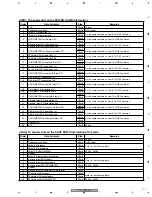
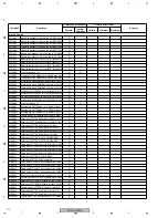
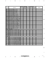
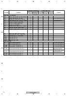
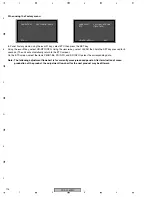
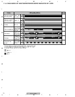
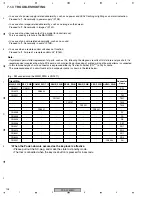
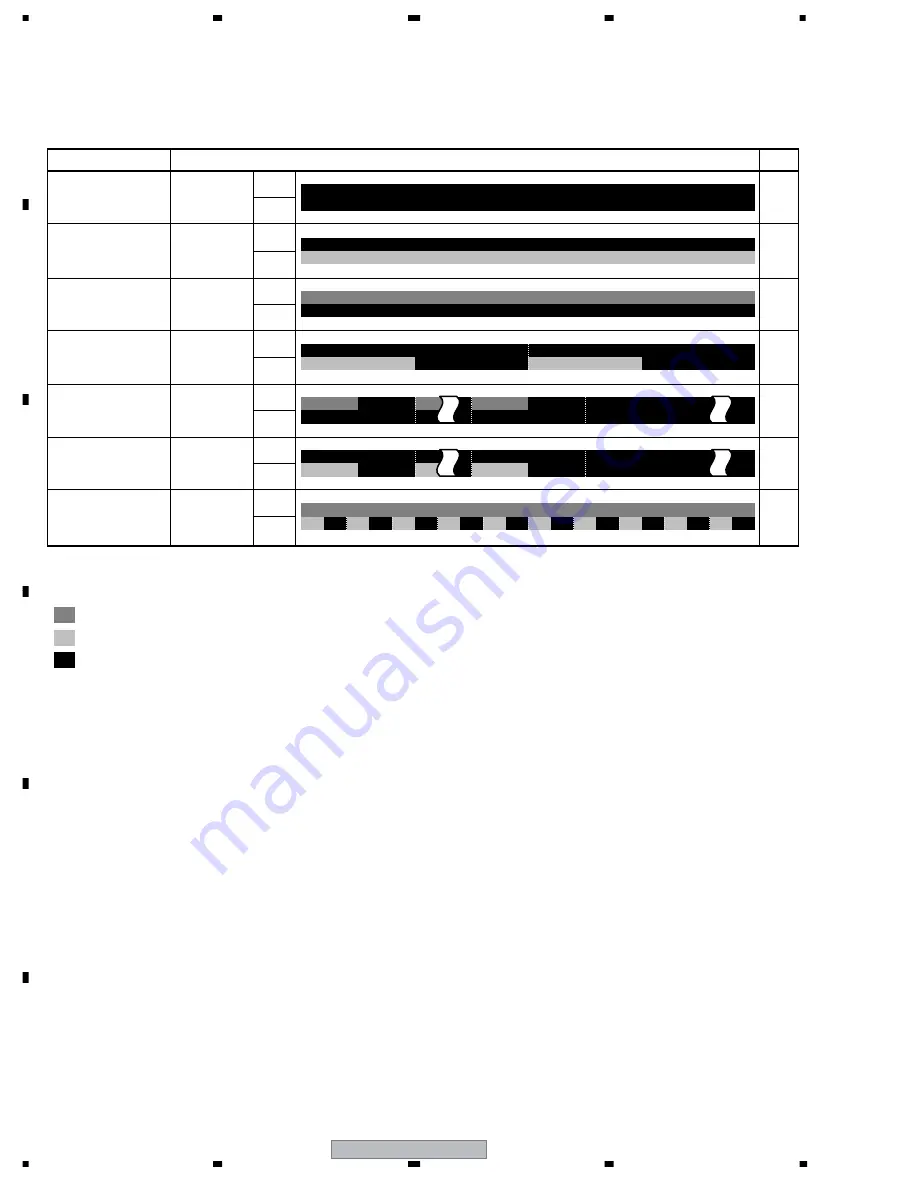
7.1.2 DIAGNOSIS OF SHUTDOWN/POWER-DOWN INDICATED BY LEDS
Not lit
Green: Lit
Red: Lit
Green
Red
Green
Red
Green
Red
Green
Red
Green
Red
Green
Red
Green
Red
*3
Standby
Green: Not lit,
Red: Not lit
Green: Lit
Red: Lit
Power on (while the
indicators are on)
Power on (while the
indicators are off)
Green flashes
at intervals of
1000 ms
Red flashes at intervals
of 500 ms for 1 to n
times *1 in one burst,
with 2500 ms of pause
between switching.
Green flashes at inter-
vals of 500 ms for 1 to n
times *2 in one burst,
with 2500 ms of pause
between switching.
Red lit, and green
flashes at intervals
of 200 ms
Power management
Power-down
Shutdown
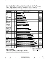
*1 For the frequency of flashing during power-down, see the "PD" sheet.
*2 For the frequency of flashing during shut down, see the "SD" sheet.
*3 Only the LEDs on the DIGITAL Assy of MD flash.
No backup copy
(panel)
Status
LED Lighting Pattern
Remarks
1000mS
1000mS
500mS
500mS
500mS
200mS
500mS
2500mS
2500mS
(Once)
(Once)
(n times)
(n times)
Содержание PDP-42MXE10
Страница 9: ...PDP 425CMX 9 5 6 7 8 5 6 7 8 C D F A B E ...
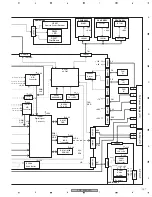
Страница 26: ...PDP 425CMX 26 1 2 3 4 1 2 3 4 C D F A B E 3 2 OVERALL CONNECTION DIAGRAM 2 2 Overall Wiring Diagram 2 2 ...
Страница 27: ...PDP 425CMX 27 5 6 7 8 5 6 7 8 C D F A B E ...
Страница 37: ...PDP 425CMX 37 5 6 7 8 5 6 7 8 C D F A B E ...
Страница 129: ...PDP 425CMX 129 5 6 7 8 5 6 7 8 C D F A B E ...
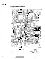
Страница 132: ...PDP 425CMX 132 1 2 3 4 1 2 3 4 C D F A B E MAIN PWB CONNECTOR WAVE FORM POINT SIDE B ...
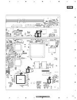
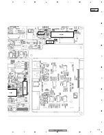
Страница 133: ...PDP 425CMX 133 5 6 7 8 5 6 7 8 C D F A B E X5008 X5008 34 35 IC6304 IC6302 29 29 IC6302 29 SIDE B ...
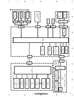
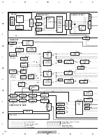
Страница 178: ...PDP 425CMX 178 1 2 3 4 1 2 3 4 C D F A B E Pin Layout Block Diagram DS90CF388VJD MD DIGITAL ASSY IC3001 LVDS Receiver ...

