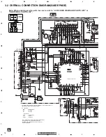
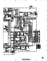
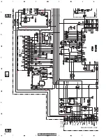
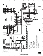
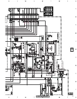
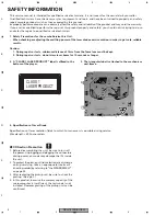
Pioneer DEH-1600R Скачать руководство пользователя страница 13


DEH-1630R/XU/EW

13

5

6

7

8

5

6

7

8

C

D

F

A

B

E


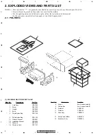
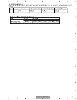
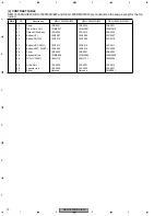
CD MECHANISM MODULE SECTION PARTS LIST


Mark No.

Description

Part No.


1

CD Core Unit(S10.1)

CWX2947


2

Connector(CN101)

CKS4182


3

Connector(CN701)

CKS4188


4

Screw

BMZ20P035FTC


5

Screw

BSZ20P040FTC


6

Screw(M2x4)

CBA1362


7

Screw(M2x3)

CBA1511


8

Screw(M2x3)

CBA1527


9

•••••


10

Washer

CBF1038


11

Washer

CBF1060


12

Spring

CBH2390


13

Spring

CBH2606


14

Spring

CBH2607


15

Spring

CBH2608


16

Spring

CBH2609


17

Spring

CBH2610


18

Spring

CBH2735


19

Spring

CBH2612


20

Spring

CBH2613


21

Spring

CBH2614


22

Spring

CBH2615


23

Spring

CBH2616


24

Spring

CBH2617


25

Spring

CBH2620


26

Spring

CBH2621


27

Spring

CBH2641


28

Spring

CBH2642


29

Spring

CBH2643


30

Spring

CBH2659


31

Spring

CBH2688

 32

•••••


33

Shaft

CLA4441


34

Frame

CNC9962


35

Frame

CNC9963


36

Bracket

CNC9966


37

Bracket

CND1895


38

Arm

CNC9968


39

Arm

CND1909


40

Lever

CND2032


41

Lever

CNC9984


42

Sheet

CNM8134


43

Collar

CNV7798


44

Guide

CNV7799


45

Arm

CNV7800


46

Rack

CNV7199


47

Holder

CNV7201


48

Holder

CNV7202


49

Arm

CNV7203


50

Gear

CNV7207


51

Gear

CNV7208


52

Gear

CNV7209


53

Gear

CNV7210


54

Gear

CNV7211


55

Gear

CNV7212


56

Rack

CNV7214


57

Arm

CNV7215


58

Arm

CNV7216


59

Guide

CNV7217


60

Roller

CNV7218


61

Gear

CNV7219


62

Arm

CNV7221


63

Arm

CNV7220


64

Arm

CNV7222


65

Damper

CNV7313


66

Damper

CNV7314


67

Arm

CNV7341


68

Arm

CNV7342


69

Guide

CNV7360


70

Guide

CNV7361


71

Holder

CNV7437


72

Arm

CNV7805


73

Gear

CNV7595


74

Damper

CNV7618


75

Motor Unit(M1)

CXB6007


76

Chassis Unit

CXC2318


77

Screw Unit

CXB8729


78

Gear Unit

CXC2397


79

Arm Unit

CXC2316


80

Arm

CND1896


81

Arm

CND1894


82

Motor Unit(M2)

CXB8933


83

Bracket

CNC9985


84

•••••


85

Screw(M2x5)

EBA1028


86

Screw

JFZ20P020FTC


87

Screw

JGZ17P022FTC


88

•••••


89

Washer

YE20FTC


90

Pickup Unit(P10)(Service)

CXX1647


91

Screw

IMS26P030FTC


92

Spring

CBL1635


93

Clamper

CNV7197


Mark No.

Description

Part No.

Содержание DEH-1600R

Страница 1: ...3 Alexandra Road 04 01 Singapore 159936 PIONEER CORPORATION 2003 DEH 1630R XU EW CRT3174 HIGH POWER CD PLAYER WITH RDS TUNER DEH 1630R XU EW DEH 1600R XU EW DEH 1600RB XU EW This service manual should be used together with the following manual s Model No Order No Mech Module Remarks CX 3110 CRT3178 S10 1 CD Mech Module Circuit Description Mech Description Disassembly For details refer to Important...

Страница 2: ...g repair or tests minimum distance of 13cm from the focus lens must be kept 2 During repair or tests do not view laser beam for 10 seconds or longer 2 A CLASS 1 LASER PRODUCT label is affixed to the bottom of the player 3 The triangular label is attached to the mechanism unit frame 4 Specifications of Laser Diode Specifications of laser radiation fields to which human access is possible during ser...

Страница 3: ...ances 5 Lubricants glues and replacement parts Appropriately applying grease or glue can maintain the product performances But improper lubrication or applying glue may lead to failures or troubles in the product By following the instructions in this manual be sure to apply the prescribed grease or glue to proper portions by the appropriate amount For replacement parts or tools the prescribed ones...

Страница 4: ...3 3 KEYBOARD UNIT 22 3 4 CD MECHANISM MODULE 24 4 PCB CONNECTION DIAGRAM 28 4 1 TUNER AMP UNIT 28 4 2 KEYBOARD UNIT 32 4 3 CD MECHANISM MODULE 34 5 ELECTRICAL PARTS LIST 36 6 ADJUSTMENT 40 6 1 CD ADJUSTMENT 40 6 2 CHECKING THE GRATING AFTER CHANGING THE PICKUP UNIT 41 6 3 ERROR MODE 43 7 GENERAL INFORMATION 44 7 1 DIAGNOSIS 44 7 1 1 DISASSEMBLY 44 7 1 2 CONNECTOR FUNCTION DESCRIPTION 48 7 2 PARTS ...

Страница 5: ...DEH 1630R XU EW 5 5 6 7 8 5 6 7 8 C D F A B E 1 SPECIFICATIONS ...

Страница 6: ...n the case of no amount instructions apply as you think it appropriate 10 1 12 6 8 9 11 7 4 3 5 2 13 14 Mark No Description Part No 1 Cord Assy CDE7059 2 Screw CBA1650 3 Handle CNC5395 4 Bush CNV3930 5 Polyethylene Bag CEG1160 6 Polyethylene Bag CEG 162 7 1 Owner s Manual YRD5001 7 2 Installation Manual YRD5006 7 3 Passport CRY1013 7 4 Warranty Card CRY1157 8 Carton See Contrast table 2 9 Contain ...

Страница 7: ...l lowing Mark NO Description DEH 1630R XU EW DEH 1600R XU EW DEH 1600RB XU EW 8 Carton YHG5002 YHG5001 YHG5009 9 Contain Box YHL5002 YHL5001 YHL5009 Owner s Manual Installation Manual Model DEH 1630R XU EW DEH 1600R XU EW DEH 1600RB XU EW Part No YRD5001 YRD5006 Language English Spanish German French Italian Dutch English Spanish German French Italian Dutch ...

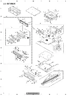
Страница 8: ...DEH 1630R XU EW 8 1 2 3 4 1 2 3 4 C D F A B E 2 2 EXTERIOR ...

Страница 9: ...CKS3581 36 Connector CN651 CKS3835 37 Connector CN621 CKS4124 38 Antenna Jack CN401 CKX1056 39 Holder CND1328 40 Heat Sink CNR1668 41 FM AM Tuner Unit CWE1645 42 Holder CND1054 43 Holder YNC5002 44 Detach Grille Assy See Contrast table 2 45 Screw BPZ20P100FZK 46 Spring CBH2210 47 Button CD EJECT YAC5001 48 Button TA EQ YAC5003 49 Button UP See Contrast table 2 50 Button DOWN See Contrast table 2 5...

Страница 10: ...Tuner Amp Unit YWM5007 YWM5001 YWM5019 44 Detach Grille Assy YXA5026 YXA5014 YXA5032 49 Button UP YAC5007 YAC5005 YAC5007 50 Button DOWN YAC5010 YAC5008 YAC5010 54 Button UP DOWN YAC5017 YAC5015 YAC5017 55 Button LEFT RIGHT YAC5020 YAC5018 YAC5020 58 Cover YNS5020 YNS5021 YNS5020 59 Keyboard Unit YWM5008 YWM5002 YWM5020 60 LCD LCD1801 CAW1779 CAW1731 YAW5006 68 Grille Unit YXA5002 YXA5001 YXA5013 ...

Страница 11: ...DEH 1630R XU EW 11 5 6 7 8 5 6 7 8 C D F A B E ...

Страница 12: ...38 23 59 87 86 5 13 34 5 5 13 44 5 C 52 53 36 4 73 29 51 18 64 76 50 10 72 75 49 77 67 27 78 60 90 48 8 17 46 6 60 11 89 43 70 14 31 65 85 66 85 31 35 14 74 85 1 2 3 R 91 12 33 61 63 21 79 57 58 62 80 13 4 86 I 45 28 7 24 47 P 41 20 40 69 39 30 P 19 56 F E 22 81 15 G 26 4 54 37 55 93 92 10 C 1GEM1024 2GEM1045 3GEM1035 1 1 1 1 1 1 1 1 2 2 2 2 1 1 1 1 1 2 2 1 3 ...

Страница 13: ...rm CNC9968 39 Arm CND1909 40 Lever CND2032 41 Lever CNC9984 42 Sheet CNM8134 43 Collar CNV7798 44 Guide CNV7799 45 Arm CNV7800 46 Rack CNV7199 47 Holder CNV7201 48 Holder CNV7202 49 Arm CNV7203 50 Gear CNV7207 51 Gear CNV7208 52 Gear CNV7209 53 Gear CNV7210 54 Gear CNV7211 55 Gear CNV7212 56 Rack CNV7214 57 Arm CNV7215 58 Arm CNV7216 59 Guide CNV7217 60 Roller CNV7218 61 Gear CNV7219 62 Arm CNV722...

Страница 14: ...CORE UNIT S10 1 C 2 16 SO 12 XSI 3R3V 48 mute X1 X2 2 21 3 SYSTEM CONTROLLER IC 601 2 2 PE5329B CN401 1 2 swvdd B UP VDD B UP CN651 Q Q Q Q992 Q991 TUNER AMP UNIT 70 X601 69 VST VCK VDT TUN L CD L 9 DPDT 8 KYDT 43 SYSPW 22 ILMPW 65 dsens A 20 15 11 17 16 14 21 RDS_CK RDS_LO RDS_DA RDS_HS LOEJ 29 CONT 28 DSCSNS 79 CLAMPSW 27 TUN 3V VCC VDD 41 VDCONT CLMP 80 STRKEY1 46 KEY2 TC7SET08FU IC 652 2 4 XSI...

Страница 15: ...P Q922 Q923 43 PW Q452 MUTE RL RL Q352 7 5 4 3 KYDT 18 20 DPDT KTDT LCD MUTE SYSTEM CONTROLLER Q951 VDD TELIN 34 FL FL RL RL VDD REGULATOR BACKUP SENSE ACC SENSE TELEPHONE MUTE SYS 8 4V REGULATOR 14 8 6 5 7 16 9 11 14 8 6 5 7 16 9 11 15 15 B CN901 CN352 BACK UP GND RR RR FR FR FL FL RL RL ACC GND BACK UP B REM FUSE 10A ACC TELMUTE B REM ldet SL TUNPCE2 TUNPCE1 TUNPDI TUNPDO 61 76 55 56 11 12 TUNPC...

Страница 16: ...NTROLLER For resistors and capacitors in the circuit diagrams their resistance values or capacitance values are expressed in codes Ex Resistors Code Practical value 123 12k ohms 103 10k ohms Capacitors Code Practical value 103 0 01uF 101 10 100uF 10V The mark found on some component parts indicates the importance of the safety factor of the part Therefore when replacing be sure to use parts of ide...

Страница 17: ...2R2 50 600µH REAR L CH REAR R CH FUSE CEK1208 10A A TUNER AMP UNIT RR RR FR FR FL FL RL RL ACC GND B REM BACK UP RR RR FR FR FL FL RL RL ACC GND B REM BACK UP TEL MUTE 3A FM 6 6dBs AM 2 9dBs CD 10 45dBs FM 32 6dBs AM 23 1dBs CD 36 45dBs Jack for the wired remote control ...

Страница 18: ...DEH 1630R XU EW 18 1 2 3 4 1 2 3 4 C D F A B E A a A b A a A a A b 1 2 C CN701 FM AM TUNER UNIT FM 15 5dBs AM 26 0dBs CD 0 35dBs ...

Страница 19: ...values or capacitance values are expressed in codes Ex Resistors Code Practical value 123 12k ohms 103 10k ohms Capacitors Code Practical value 103 0 01uF 101 10 100uF 10V The mark found on some component parts indicates the importance of the safety factor of the part Therefore when replacing be sure to use parts of identical designation B CN1801 TUNER UNIT ...

Страница 20: ... EW 20 1 2 3 4 1 2 3 4 C D F A B E A a A b A b 1 2 332 16 TDA7386 2R2 50 600µH REAR L CH REAR R CH FUSE CEK1208 10A A TUNER AMP UNIT GND BACK UP 3A FM 6 6dBs AM 2 9dBs CD 10 45dBs FM 32 6dBs AM 23 1dBs CD 36 45dBs ...

Страница 21: ...8 5 6 7 8 C D F A B E A a A b A b 3 600µH FUSE CEK1208 10A RR RR FR FR FL FL RL RL ACC GND B REM BACK UP RR RR FR FR FL FL RL RL ACC GND B REM BACK UP TEL MUTE Jack for the wired remote control FM 32 6dBs AM 23 1dBs CD 36 45dBs ...

Страница 22: ...XU EW IL1801 1802 D1803 18 ILM COLOUR DEH 1630R XU EW For resistors and capacitors in the circuit diagrams their resistance values or capacitance values are expressed in codes Ex Resistors Code Practical value 123 12k ohms 103 10k ohms Capacitors Code Practical value 103 0 01uF 101 10 100uF 10V ...

Страница 23: ...DEH 1630R XU EW 23 5 6 7 8 5 6 7 8 C D F A B E B CL 490S WF SD CL 490S WF SD 803 1809 R1816 1818 40mA 14V LCD1801 YAW5006 CAW1779 CAW1731 B KEYBOARD UNIT A CN831 ...

Страница 24: ...E 3 4 CD MECHANISM MODULE C PICKUP UNIT P10 SERVICE BA5835FP R1 R1 R1 M1 CXB6007 SPINDLE MOTOR M2 CXB8933 LOADING CARRIAGE MOTOR RF MOTOR DRIVER 3 3V REGULATOR F F F F F F F F F F F F F T S C T T S S C C C C S S T T T T T T T T T T 1 7 8 3 6 5 9 0 ...

Страница 25: ...WITCH ON OFF S903 DSCSNS SWITCH ON OFF S904 12EJ SWITCH ON OFF S905 8EJ SWITCH ON OFF The underlined indicates the switch position A C CN651 CD CORE UNIT S10 1 RF AMP SERVO DSP DAC LPF SIGNAL LINE FOCUS SERVO LINE TRACKING SERVO LINE CARRIAGE SERVO LINE SPINDLE SERVO LINE F T C S S C C S C T F S C T F 3 6 5 4 2 9 ...

Страница 26: ... Spindle waveform during Play Ref REFO Mode Normal RFAGC 500mV div 0 5µs div Ref REFO Mode Normal MDX 5 SIN 500mV div 1V div 5µs div Spindle waveform during Play Magnified RF eye pattern Ref REFO Mode Normal 8 FIN FE 500mV div 500mV div 200ms div Focus Search Ref REFO Mode TEST RFAGC 0 TE 7 TIN 1V div 500mV div 500mV div 500µs div Ref REFO Mode TEST 0 TE RFAGC 500mV div 500mV div 2ms div When Trac...

Страница 27: ... AGND Mode Normal 1 DSCSNS 2 CLCONT 3 LOEJ 5V div 5V div 5V div 200ms div Ref GND Mode Normal 1 DSCSNS 2 CLCONT 3 LOEJ 5V div 5V div 5V div 200ms div When Eject 12cm CD When Eject 8cm CD Ref GND Mode Normal RFAGC 0 TE 6 CIN 5 SIN 1V div 1V div 500mV div 2V div 500µs div When reproducing scratch 1mm During inside outside search outer circumference inner circumference Ref REFO Mode Normal RFAGC 0 TE...

Страница 28: ...nector P C Board Chip Part SIDE B SIDE A NOTE FOR PCB DIAGRAMS 1 The parts mounted on this PCB include all necessary parts for several destination For further information for respective destinations be sure to check with the schematic dia gram 2 Viewpoint of PCB diagrams CORD ASSY B C CN701 JACK FOR THE WIRED REMOTE CONTROL ...

Страница 29: ...DEH 1630R XU EW 29 5 6 7 8 5 6 7 8 C D F A B E A SIDE A FRONT B CN1801 FM AM TUNER UNIT ANTENNA JACK REAR OUTPUT ...

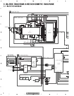
Страница 30: ...DEH 1630R XU EW 30 1 2 3 4 1 2 3 4 C D F A B E A A TUNER AMP UNIT ...

Страница 31: ...DEH 1630R XU EW 31 5 6 7 8 5 6 7 8 C D F A B E A SIDE B ...

Страница 32: ... 1630R XU EW 32 1 2 3 4 1 2 3 4 C D F A B E 4 2 KEYBOARD UNIT B B KEYBOARD UNIT B KEYBOARD UNIT SIDE A SIDE B A CN831 TA VOL EQ EQ VOL VOL 1 SOURCE VOL 2 3 5 6 4 LOUD BAND BAND AUDIO EJECT EJECT LOCAL BSM ...

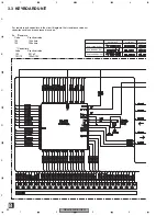
Страница 33: ...DEH 1630R XU EW 33 5 6 7 8 5 6 7 8 C D F A B E ...

Страница 34: ...DEH 1630R XU EW 34 1 2 3 4 1 2 3 4 C D F A B E 4 3 CD MECHANISM MODULE C C CD CORE UNIT S10 1 SIDE A A CN651 PICKUP UNIT P10 SERVICE M1 SPINDLE MOTOR M2 LOADING CARRIAGE MOTOR HOME ...

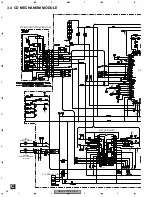
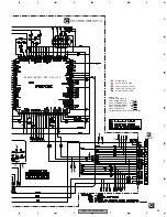
Страница 35: ...DEH 1630R XU EW 35 5 6 7 8 5 6 7 8 C D F A B E C C CD CORE UNIT S10 1 SIDE B CLAMP DSCSNS 8EJ 12EJ ...

Страница 36: ...551 Diode S5688G D 552 Diode S5688G D 831 Diode 1SS133 D 832 Diode 1SS133 D 833 Diode 1SS133 D 834 Diode 1SS133 D 835 Diode 1SS133 D 836 Diode 1SS133 D 901 Diode S5688G D 902 Diode S5688G D 911 Diode S5688G D 912 Diode HZS6L B2 D 921 Diode HZS9L B3 D 931 Diode HZS7L C3 D 932 Diode HZS7L A1 D 951 Diode DAN202U D 981 Diode S5688G D 982 Diode S5688G D 983 Diode S5688G D 991 Diode HZS9L B1 L 151 Induc...

Страница 37: ...4PU221J R 993 RS1 16S222J R 994 RS1 16S472J CAPACITORS C 151 CKSRYB224K16 Circuit Symbol and No Part No C 152 CKSRYB224K16 C 153 CKSRYB105K10 C 154 CKSRYB105K10 C 155 CEJQ4R7M35 C 156 CEJQ4R7M35 C 157 CKSRYB153K50 C 158 CKSRYB153K50 C 161 CCSRCH100D50 C 162 CCSRCH100D50 C 163 CCSRCH100D50 C 164 CCSRCH100D50 C 165 CKSRYB104K16 C 166 CEJQ470M10 C 167 CEJQ100M16 C 301 CFTNA224J50 C 302 CFTNA224J50 C ...

Страница 38: ...1801 IC PD6340A D 1801 Diode MA152WK D 1802 Diode MA152WA D 1803 LED SML 310PT D 1804 LED SML 310PT Circuit Symbol and No Part No D 1805 LED SML 310PT D 1806 LED SML 310PT D 1807 LED SML 310PT D 1808 LED SML 310PT D 1809 LED SML 310PT D 1810 LED CL 490S WF SD D 1811 LED CL 490S WF SD X 1801 Ceramic Resonator 5 00MHz CSS1547 IL 1801 Lamp 40mA 14V CEL1651 IL 1802 Lamp 40mA 14V CEL1651 LCD1801 LCD CA...

Страница 39: ...RS1 16S273J CAPACITORS C 101 CKSRYB104K16 C 102 CKSRYB104K16 C 103 100µF 16V CCH1504 C 104 47µF 6 3V CCH1506 C 108 CKSRYB104K16 C 109 CKSRYB104K16 C 201 CKSRYB104K16 C 202 CKSRYB471K50 C 205 22µF 6 3V CCH1507 C 206 CKSRYB103K25 C 207 CKSRYB104K16 C 209 CKSRYB104K16 C 210 CKSRYB104K16 C 211 CKSRYB104K16 Circuit Symbol and No Part No C 212 CKSRYB104K16 C 213 CKSRYB332K50 C 214 CKSRYB473K25 C 215 CKS...

Страница 40: ...e protections will not work Avoid applying any mechanical or electrical shock to the mechanism during adjustment The RFI and RFO signals with a wide frequency range are easy to oscillate When observing the signals insert a resistor of 1k ohms in series The load and eject operation is not guarantied with the mechanism upside down If the mechanism is blocked due to mistaken eject operation reset the...

Страница 41: ...and switch the 3V regulator on 2 Using the and buttons move the PU unit to the innermost track 3 Press key 3 to close focus the display should read 91 Press key 2 to implement the tracking balance adjustment the display should now read 81 Press key 3 The display will change returning to 81 on the fourth press 4 As shown in the diagram above monitor the LPF outputs using the oscilloscope and check ...

Страница 42: ...DEH 1630R XU EW 42 1 2 3 4 1 2 3 4 C D F A B E Grating waveform 45 0 75 60 30 90 Ech Xch 20mV div AC Fch Ych 20mV div AC ...

Страница 43: ... or CRG move mechanism Communication error between microcomputer and SERVO LSI 11 Electricity Focus Servo NG Focusing not available Stains on rear side of disc or excessive vibrations on REWRITABLE 12 Electricity Spindle Lock NG Spindle not locked Sub code is strange not readable Subcode NG Failure on spindle stains or damages on disc or excessive vibrations A disc not containing CD R data is foun...

Страница 44: ... 1 1 Remove the Case CD Mechanism Module 1 1 1 1 Fig 2 Tuner Amp Unit Removing the Tuner Amp Unit Fig 2 Remove the screw 1 Remove the four screws Disconnect the connector and then remove the CD Mechanism Module 2 Release the two latchs and then remove the Grille Assy 2 2 1 2 2 2 3 3 3 4 Remove the three screws 2 Straighten the tabs at three locations indicated 3 Remove the screw and then remove th...

Страница 45: ...1 Assemble them in order from 1 to 8 See the figure below 2 After that bend the crows 7 in total until they get the right angles with the marks printed on 8 Note If 5 is not set collectly defective contact may occur on 6 To avoid this problem hold 5 using 7 just before putting 8 ...

Страница 46: ...e two springs C and the four screws 2 To remove the upper frame open it on the fulcrum A 3 While lifting the carriage mechanism remove the three dampers 4 With the frames removed insert the connectors coming from the main unit and eject the disc Caution Before installing the carriage mechanism in the frames be sure to apply some alcohol to the dampers and set the mechanism to the clamp mode Do not...

Страница 47: ...ad wires from the inner holder 4 Remove the washer styling holder change arm and pickup lock arm 5 While releasing from the hook of the inner holder lift the end of the feed screw Caution In assembling move the planet gear to the load eject position before setting the feed screw in the inner holder Shorting Solder Planet Gear Change Arm Inner Holder Styling Holder Feed Screw Washer Pickup Lock Arm...

Страница 48: ...E 7 1 2 CONNECTOR FUNCTION DESCRIPTION 1 0 A 1 3 5 7 9 11 13 15 2 4 6 8 10 12 14 16 Pin No 1 2 3 4 5 6 7 8 FR RR FR RR FL RL FL RL Pin No 9 10 11 12 13 14 15 16 MUTE B REMOTE ACC GND B UP ANTENNA JACK REAR OUTPUT JACK FOR THE WIRED REMOTE CONTROL ...

Страница 49: ...nge output Driver input select output Not used Stand by output GND Telephone mute output Not used ROM collection data output Not used During RDS data reception output VD control output Not used System power supply control output Not used Beep tone output Key data input Remote control Not used System mute output Not used Strobe pulse output for electronic volume Data output for electronic volume Cl...

Страница 50: ...ut Grille detach sense input ATAPI HOST interrupt request input GND Power supply Crystal oscillator connection pin Crystal oscillator connection pin Connect to GND Not used Connect to GND Power supply Positive power supply terminal for analog circuit SD level input from tuner Not used VD power supply voltage sense input CD DISC sense input Key data Remote control IC s marked by are MOS type Be car...

Страница 51: ...Key data input analogue input 17 REW I Remote control reception input 18 DPDT I Display data input 19 NC Not used 20 KYDT O Key data output 21 MODA GND 22 X0 Crystal oscillator connection pin 23 X1 Crystal oscillator connection pin 24 VSS GND 25 26 KDT2 3 I Key data input 27 NC Not used 28 KST4 O Key strobe output 29 32 NC Not used 33 55 SEG35 13 O LCD segment output 56 VDD Power supply 57 64 SEG1...

Страница 52: ...27 C1D1 O Information on error correction 28 C1D2 O Information on error correction 29 C2D1 O Information on error correction 30 C2D2 O Information on error correction 31 C2D3 O Information on error correction 32 LOCK O Output of LOCK 33 MIRR O MIRR signal 34 HOLD O HOLD signal 35 PLCK O Output of PLCK 36 C16M O Output of 16 9344MHz 37 DGND Ground for digital circuits 38 TX O DAI output 39 EMPH O ...

Страница 53: ... Analog tests 80 C3T Connection to the capacitor for detecting 3T 81 AGND Ground for the analog system 82 A I Input of A 83 C I Input of C 84 B I Input of B 85 D I Input of D 86 F I Input of F 87 E I Input of E 88 VREFIN I Photo detector input bias voltage 89 AVDD Power supply for the analog system 90 REFOUT O Output of reference voltage 91 REFC Connected to the capacitor for output of REFOUT 92 F...

Страница 54: ...wer supply pin for CH1 CH2 and CH3 at Power stage 11 VO1 Driver CH1 Negative output 12 VO1 Driver CH2 Positive output 13 VO2 Driver CH2 Negative output 14 VO2 Driver CH2 Positive output 15 VO3 Driver CH2 Positive output 16 VO3 Driver CH2 Negative output 17 VO4 Driver CH4 Positive output 18 VO4 Driver CH4 Negative output 19 POWVCC2 Power supply pin for CH4 at Power stage 20 GND Ground pin 21 CNT Co...

Страница 55: ...upply Power supply for EEPROM pin 13 is connected with a power supply of micro computer 14 DO O data out Data output 15 DGND digital ground Ground of digital block 16 NC non connection Not used 17 VDD_3 3 power supply The power supply for digital block 3 3V 0 2V 18 RDS_CK O RDS clock Output of RDS clock 2 5V 19 RDS_DATA O RDS data Output of RDS data 2 5V 20 RDS_LOCK O RDS lock Output unit High act...

Страница 56: ... F A B E 7 2 2 DISPLAY COMMON SEGMENT LCD CAW1779 DEH 1630R XU EW CAW1731 DEH 1600R XU EW 1 2 3 4 5 6 7 8 9 0 33 34 36 37 38 COM3 COM2 COM1 COM0 COM3 COM2 COM1 COM0 35 39 32 31 30 29 28 27 26 25 24 23 22 21 20 19 18 17 16 15 14 13 12 11 10 ...

Страница 57: ...5 6 7 8 5 6 7 8 C D F A B E COMMON SEGMENT LCD YAW5006 DEH 1600RB XU EW COM3 COM2 COM1 COM0 0 COM3 COM2 COM1 COM0 1 2 3 4 5 6 7 8 9 10 11 12 13 14 15 16 17 18 19 20 21 22 23 24 25 26 27 28 29 30 31 32 33 34 35 36 37 38 39 ...

Страница 58: ...NS Pin 65 swvdd L Pin 21 Source keys operative Completes power on operation After that proceed to each source operation SYSPW H Pin 43 Starts communication with Grille microcomputer Source ON 300ms 300ms In case of the above signal the communication with Grille microcomputer may fail If the time interval is not 300msec the oscillator may be defective ...

Страница 59: ...C D F A B E 7 4 CLEANING Before shipping out the product be sure to clean the following portions by using the prescribed cleaning tools Portions to be cleaned Cleaning tools CD pickup lenses Cleaning liquid GEM1004 Cleaning paper GED 008 ...

Страница 60: ...DEH 1630R XU EW 60 1 2 3 4 1 2 3 4 C D F A B E 8 OPERATIONS ...

Страница 61: ...DEH 1630R XU EW 61 5 6 7 8 5 6 7 8 C D F A B E ...

Страница 62: ...1 2 3 4 C D F A B E CBA1488 CBA1488 About the fixing screws for the front front panel panel Fixing screw If you do not operate the Removing and Attaching the use the sup plied fixing fixing f scr s fi the front panel to this unit ...

Страница 63: ...ay be different In this case be sure to connect 2 to 5 and 4 to 3 6 2 This Product 3 Antenna jack 15 Yellow black If you use a cellular telephone connect it via the Audio Mute lead on the cellular telephone If not keep the Audio Mute lead free of any connections 17 Connecting cords with RCA pin plugs sold separately 22 Blue white 6 23 The pin position of the ISO connector will differ depends on th...

Отзывы: