PSS u2 ES 4DO SR 0.5A
Operating Manual-1004553-EN-01
}
Control system PSS u2
Remote I/O system PSS u2
Страница 1: ...PSS u2 ES 4DO SR 0 5A Operating Manual 1004553 EN 01 Control system PSS u2 Remote I O system PSS u2...
Страница 2: ...nta tion will be gratefully received Source code from third party manufacturers or open source software has been used for some components The relevant licence information is available on the Internet...
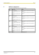
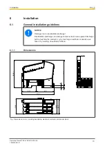
Страница 3: ...m 10 4 2 Supply 10 4 3 Integrated protection mechanisms 10 4 4 Outputs 10 4 5 Reaction times 11 4 6 Energy saving functions 11 Section 5 Address assignment 12 Section 6 Installation 13 6 1 General ins...
Страница 4: ...Contents Operating Manual PSS u2 ES 4DO SR 0 5A 1004553 EN 01 4 Section 10 Order reference 25 10 1 Product 25 10 2 Accessories 25...
Страница 5: ...ommission the product if you have read and understood this document The document should be retained for future ref erence Please refer to the PSS u2 Installation Manual 1 3 Definition of symbols Infor...
Страница 6: ...uation in which the product or devices could be dam aged and also provides information on preventive measures that can be taken It also highlights areas within the text that are of particular import a...
Страница 7: ...carrier unit for the electronic modules The terminal block is plugged into the electronic modules and is used to connect the field wiring Details of the terminal blocks that can be used are available...
Страница 8: ...INFORMATION The module is supported by PASconfig from version 2 0 0 We recommend that you always use the latest version download from www pilz com 3 3 Safety regulations 3 3 1 Use of qualified person...
Страница 9: ...ich it is intended Damage can be attributed to not having followed the guidelines in the manual Operating personnel are not suitably qualified Any type of modification has been made e g exchanging com...
Страница 10: ...ring The module provides the following diagnostic data Start up error Configuration error ST communication error Temperature error too warm Temperature error too hot 4 4 Outputs The module has 4 relay...
Страница 11: ...saving levels are controlled by the head module and are not configurable The module supports the following energy saving levels Switching off the LEDs The LEDs have two energy saving levels Switching...
Страница 12: ...1 Output data O1 Changeover contact O1 22 O1 21 Changeover contact O1 24 O1 21 0 Changeover contact O1 22 and O1 21 is closed 1 Changeover contact O1 24 and O1 21 is closed Bit 2 Output data O2 Change...
Страница 13: ...ectrostatic discharge Electrostatic discharge can damage components Ensure against discharge before touching the product e g by touching an earthed conductive sur face or by wearing an earthed armband...
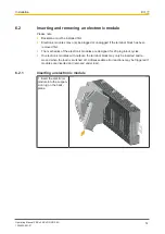
Страница 14: ...block has been removed first The mechanics of the electronic modules are designed for 20 plug in out cycles On electronic modules with outputs the terminal block may only be inserted and re moved when...
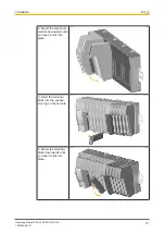
Страница 15: ...O SR 0 5A 1004553 EN 01 15 2 Swivel the electronic module downwards until you hear it click into place 3 Insert the terminal block into the suspen sion lug on the module 4 Swivel the terminal block do...
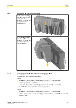
Страница 16: ...upwards 6 2 3 Changing an electronic module during operation An electronic module can be hot swapped Effects Module bus communication between the other modules is not interrupted The configuration dat...
Страница 17: ...4DO SR 0 5A 1004553 EN 01 17 On electronic modules with outputs the terminal block may only be inserted and re moved when the load is switched off Unforeseeable error reactions may be triggered if mod...
Страница 18: ...1 1 Connection mechanism for terminal blocks Procedure Use a flat head screwdriver Strip the wire back 9 mm Feed the stripped cable as far as it will go into the opening for the spring loaded ter min...
Страница 19: ...l 7 O1 22 Terminal 8 O1 21 Changeover contact 1 O1 22 O1 21 Changeover contact 2 O1 24 O1 21 Output O2 Terminal 9 O2 34 Terminal 10 O2 31 Terminal 11 O2 32 Terminal 12 O2 31 Changeover contact 1 O2 32...
Страница 20: ...us display 2 Terminal status display The module can detect the following errors 1 Col our 1 2 Col our 2 Meaning Further information Module not ready for operation Green Module ready for operation Gree...
Страница 21: ...missing temperature error Too hot 1 See module s diagnostic log 1 There are two levels of overtemperature Too warm If the module temperature exceeds a threshold value then a warning is sent to the he...
Страница 22: ...g time for relay output tProcOM when signal changes from 1 to 0 10 ms Max processing time for relay output tProcOM when signal changes from 0 to 1 10 ms Contact material AgNi Environmental data Climat...
Страница 23: ...l isolation Functional insulation Rated surge voltage 1500 V Potential isolation between Relay output and periphery supply Type of potential isolation Functional insulation Rated surge voltage 1500 V...
Страница 24: ...ife graphs The service life graphs indicate the number of cycles from which failures due to wear must be expected The wear is mainly caused by the electrical load the mechanical load is negli gible Fi...
Страница 25: ...A LC E1 10 pcs Label holder 23 5 x 10 5 mm 10 pieces 328 910 PSS u2 A LC E2 10 pcs Label holder 103 x 10 5 mm 10 pieces 328 911 PSS u2 A LA E1 10 pcs Labelling strips 23 5 x 10 5 mm 10 x DIN A4 sheet...
Страница 26: ...PSS u2 ES 4DO SR 0 5A 1004553 EN 01 26 Shield connection element Product type Features Order no PSS u2 A SH 4 Shield connection element for module rack with 4 slots 328 820 PSS u2 A LC B4 Inscription...