


Installation
Operating Manual PSEN ml sa 1.1/2.1/2.2, PSEN ml DHM
1005457-EN-02
| 39
8
Installation
8.1
Important information
NOTICE
Install the safety switch and actuator so that the possibilities of defeat are
reduced to a minimum (see guidelines for reducing the possibilities for de-
feating interlocking devices in EN ISO 14119).
NOTICE
Install safety switch and actuator so that it is not possible to reach through
with hand or finger.
}
The fastening of safety switch and actuator has to be sufficiently stable to ensure the
proper operation of the safety switch and the actuator.
}
Prevent the safety switch and actuator being exposed to heavy shock or vibration.
}
Installation of the safety switch and actuator must be concealed.
}
The mounting surfaces for safety switches and actuators can have a max. unevenness of
0.5 mm.
}
The actuator must rest flush on the mounting surface.
}
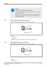
The safety switch and actuator should be installed opposite each other in parallel.
}
After installation, at least one of the auxiliary releases/escape releases must be operated.
}
Use the same type of screw to attach the safety switch and actuator.
}
Use non-removable flat head locking screws to attach the safety switch and actuator (e.g.
cheese-head or pan head screws) or rivets.
}
For a minimum screw depth of 6 mm, M5 screws and M8 screws with resistance class 8.8
should be used to attach the safety switch and actuator.
}
Prevent self-loosening of the fastening elements,
– On the safety switch: By complying with the max. torque setting (see
details [
– On the actuator: By complying with the max. torque setting (see
details [
) and medium-strength threadlockers.
}
Torque setting: Please note the information provided under
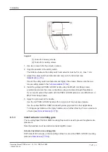
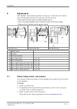
Don’t fully tighten the safety screws until the safety switches and actuators are correctly
aligned and the function has been tested (see
}
Installation of the safety switch and actuator must be concealed.