


Installation
Operating Manual PSEN ml s 1.1/2.1/2.2
1004710-EN-05
| 40
8.2.2
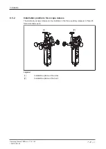
Installation on swing gate
[1]
[2]
[2]
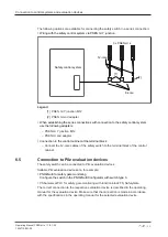
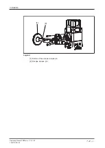
Fig.: Swing gate with internal and external hinge
Legend
[1]
Safety switch on gate frame
[2]
Actuator, installed on swing gate
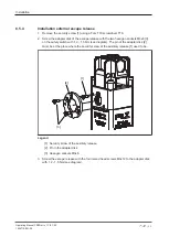
1. Install the safety switch with the
fixing screws of the safety switch in parallel to the
on the gate frame.
2. Use two M5 screws to fix the actuator to the gate.
The actuator should engage smoothly into the safety switch.
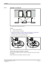
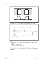
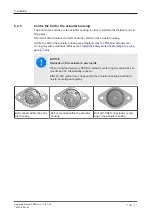
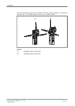
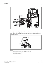
Install the safety switch horizontally at a swing gate
Depending on the installation boundary conditions, a larger gate radius may be required
(see diagram).
Please contact Pilz when smaller gate radiuses are required.