PSEN cs6.2 M12/8
Operating Manual PSEN cs6.2 M12/8
1003425-EN-06
17
Wiring
Please note:
}
}
The max. cable length l
max
in the input circuit is calculated from
–
the max. cable capacitance at the safety outputs (see
).
–
the minimum permitted supply voltage at the sensor (19.2 V).
}
The power supply must meet the regulations for extra low voltages with protective sep-
aration (SELV, PELV).
}
The inputs and outputs of the safety switch must have a protective separation to
voltages over 60 VDC.
INFORMATION
Only use safety relays with a 24 VDC supply voltage. Safety relays with a
wide-range power supply or in AC device versions have internal potential
isolation and are not suitable as evaluation devices.
}
The supply voltage to the safety switch must be protected with a 2 A to 4 A quick-acting
fuse.
}
Ensure the wiring and EMC requirements of EN 60204-1 are met.
}
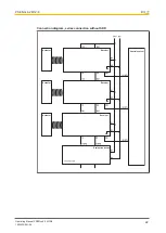
When connecting in series, consider the requirements of manipulation protection and
the protection against bypassing or from overriding the safety switch (EN ISO 14119).
}
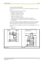
When the safety inputs of the safety switch are controlled by an upstream device, and
they are not wired with 24 V,
–
They must be monitored for shorts across the contacts in dependence of the Per-
formance Level or SIL level to be achieved
or
–
The the faults at the safety inputs that can occur by shorts across contact will have
to be excluded by suitable measures (e.g. wiring in accordance with EN 602041).
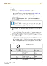
Pin assignment, connector and cable
8-pin M12 connector
PIN
Connection
designation
Function
Wire colour
1
S21
Input, channel 2
white
2
A1
+24 VUB
brown
3
12
Output, channel1
green
4
22
Output, channel2
yellow
5
Y32
Signal output/diagnostic output
grey
6
S11
Input, channel 1
pink


