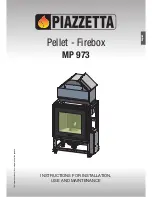
Pellet - Firebox
MP 973
INSTRUCTIONS FOR INSTALLATION,
USE AND MAINTENANCE
The instruction manual is an integral part of the product.
English
Страница 1: ...Pellet Firebox MP 973 INSTRUCTIONS FOR INSTALLATION USE AND MAINTENANCE The instruction manual is an integral part of the product English...
Страница 2: ...at first time of cleaning The stove must be assembled by at least two persons Connect the appliance to the electricity supply only after it has been connected by an expert to the flue system See the g...
Страница 3: ...6 0 USE 26 6 1 Loading the pellets 26 6 2 Remote control 26 6 3 Lighting for the first time 27 6 4 Start up and normal functioning 28 6 5 Possible problems and solutions 32 6 6 Control panel 36 6 7 S...
Страница 4: ...N TO FLUE SAFETY DISTANCES SOOT REMOVAL INSPECTION HOLE POWER SUPPLY FRESH AIR INTAKE CHECK OF FLOOR LOAD BEARING CAPACITY MULTIFUOCO VENTILATION SYSTEM MINIMUM SAFETY DISTANCES LINING WALL HOOD GRILL...
Страница 5: ...f at least 20 mm and a maximum ratio between the sides of 1 5 Fig 4 the walls must be smooth if possible and without narrowing bends must be regular and without discontinuity Fig 6 d d It is forbidden...
Страница 6: ...om any buildings or other obstacles that are higher than the chimney stack 50 centimetres higher than any obstacles located at a distance less than 5 metres outside the reflux area The size and shape...
Страница 7: ...irements given above d d Combustion air must not be taken from adjacent rooms used as a garage or a combustible materials store or for activities posing a fire hazard The appliance should be installed...
Страница 8: ...lings position of the rooms to be heated in relation to other adjacent heated or unheated rooms External factors geographical position average outdoor temperature exposure wind speed latitude altitude...
Страница 9: ...ese indications could result in fire Please refer to the section Technical specifications and installation instructions for the values a a Distance F for information regarding the safety distances ins...
Страница 10: ...inal diameter of 80 or 100 mm for pipes which run inside the flue maximum diameter 150 mm can be used The male female connectors must have a minimum length of 50 mm The diameter of the pipes depends o...
Страница 11: ...ing into account that the pipes and bends must be made in compliance with current regulations In this case however Gruppo Piazzetta S p A only guarantees trouble free operation for parts that it manuf...
Страница 12: ...on system and it is therefore necessary to maintain the safety distances from flammable materials such as flammable ceilings or walls ledges beams furniture curtains etc The hood grille must be instal...
Страница 13: ...tions and European and national standards as well as local regulations a a When a flue pipe passes through a wall or a ceiling special installation methods must be applied protection thermal insulatio...
Страница 14: ...see section MULTICOMFORT front hot air outlet at bottom with two baffles to separate flow two outlets at rear for ducting if required see section MULTIFUOCO SYSTEM DT2010314 01 2 1 Technical characte...
Страница 15: ...cm2 350 350 CERTIFICATION DATA Test report N RRF85133486 Notified laboratory N 1625 TECHNICAL DATA FOR FLUE CALCULATIONS Smoke flow g s 12 40 5 36 Average temp smoke in gas outlet pipe C 248 0 190 0 M...
Страница 16: ...ote control Provided Door handle tool Provided Grate baffle plate Provided Thermodur spray paint can Provided Door in plasterboard for lining wall Optional Front pellet feed kit Optional Pipes and elb...
Страница 17: ...e kept in the position according to the directions shown by the diagrams and notices on the pack if ropes straps or chains are used ensure that they are able to take the weight of the pack and that th...
Страница 18: ...tion of the lining wall and after all the building works have been stabilised and tested the whole installation must in any case be tested to check correct operation following the instructions given i...
Страница 19: ...ed together with the union Fig 30 The standard product comes with the electronic boards fitted on the right side of the stove If necessary the electronic board support can however be placed on the lef...
Страница 20: ...d secure it using the 2 previously removed screws Remove the plug 8 from the left side of the thermostat housing insert the thermostat bulb and secure it with the relative clip provided Refit the plug...
Страница 21: ...floor standing heat distribution system offers notable advantages even spread of temperatures Fig 39 The hot air produced is propelled by two fans and distributed via the grille at the back of the st...
Страница 22: ...directed to the front by one fan In addition a second fan directs heat to the rear allowing for a second room to be heated a a For the example shown in Figure 41 with single ducting it is necessary to...
Страница 23: ...ductivity 100 C 0 050 W mK Material with code AGI Q132 or DIN 18895 is allowed for thermal insulation a a If the insulating material is not enclosed under the floor or within the walls it must be fixe...
Страница 24: ...t Fig 50 Fit the Y element to the fan outlet using the screws provided in the kit Fig 50 Fit the second hose to the Y element using the clip provided in the kit Fig 50 Repeat the above steps for the o...
Страница 25: ...ay be connected to the DB9 serial socket DT2011810 01 5 7 Electrical connections and controls 1 2 3 7 Fig 52 1 External jack for connection of room sensor 2 Socket for power lead 3 Pipe tap 4 Cable gl...
Страница 26: ...per it is advisable to tear off the edge of the sack and empty the sack directly into the hopper This makes filling easier and avoids pouring pellets on top of the stove a a Do not allow sawdust to ac...
Страница 27: ...hen the safety system is activated 20 Display FLAT BATTERY Shows that the battery is flat or running down DT2010082 06 6 3 Lighting for the first time Before lighting the stove for the first time chec...
Страница 28: ...T A R T P H A S E I 1 2 0 0 2 2 c S T A R T P H A S E I I 1 2 0 0 2 2 c 1 1 1 START PHASE I The smoke aspirator is activated The auger is engaged and begins to convey pellets to the brazier If during...
Страница 29: ...To maximise the potential of the Multifuoco function read the sections MULTIFUOCO SYSTEM and MULTICOMFORT OPERATION 1 2 0 0 2 2 c P 3 2 2 6 c 1 2 0 0 2 6 c 1 1 1 1 1 L E V E L P 2 S E T P O W E R S E...
Страница 30: ...with a device which informs of the lack of fuel in the hopper Where the amount of fuel reaches the minimum level the unit works at minimum power and the message SHORT ON PELLET appears on the display...
Страница 31: ...T S t o p 1 T E R M E X T O K 1 0 3 0 t o n 1 O F F T 1 0 3 0 2 4 c 1 P 2 1 0 3 0 2 2 c 1 0 3 0 2 4 c 1 L E V E L P 4 O K 1 E X T E R N A L T H E R M O S T M o d u l a t 1 E X T E R N A L T H E R M O...
Страница 32: ...1 E M P T Y B R A Z I E R B R A Z I E R E M P T I E D 1 2 0 0 2 2 c 1 B R A Z I E R E M P T I E D N O 2 2 c 1 Y E S 2 2 c 1 1 0 3 0 O F F 1 The appliance shuts off To re start the stove see the STOVE...
Страница 33: ...table S H U T D O W N 1 2 0 0 2 2 c 1 E M P T Y B R A Z I E R 1 2 0 0 2 2 c 1 If during start up the stove does not reach the start temperature limit within the specified time the message NO LIT E14...
Страница 34: ...pears on the display If the stove is to be started again by pressing the ON OFF key the message COOLING appears on the display this indicates that you must wait for the necessary cooling period When i...
Страница 35: ...ton ON OFF the message WAIT COOLING appears followed by the message EMPTY BRAZIER To restart the appliance see the section START UP AND NORMAL OPERATION Power failure during operation WITH CHRONO SETT...
Страница 36: ...key for several seconds the alarm signal will stop wait until you are sure that combustion of any pellets left in the grate has ceased wait for the stove to cool then check for and remove whatever ha...
Страница 37: ...the display turns off after approximately 20 seconds SET OPT ESC MENU Remote control MENU SELECT LANGUAGE SET CLOCK DAY MONDAY DAY TUESDAY DAY WEDNESDAY DAY THURSDAY DAY FRIDAY DAY SATURDAY DAY SUNDAY...
Страница 38: ...1 Set the current day of the month Press the SELECT MENU key and set the day of the month confirm by pressing the SET key S E T C L O C K D A Y M O N D A Y H O U R S C L O C K 1 2 M I N U T E S C L O...
Страница 39: ...2 0 0 2 2 I N L O A D c A U G E R L O A D E D 1 1 1 1 DT2040101 00 DT2010242 05 6 11 Thermostat The function of the thermostat is to allow the user to program the stove so that it is switched on and o...
Страница 40: ...f 1 1 1 1 1 1 S E T C H R O N O P R O G R A M D A Y E N A B L E D A Y S T A R T D P R O G R A M 1 S T O P D P R O G R A M 1 S T O P D P R O G R A M 1 S E T D P O W E R 1 Set shutdown time for 1st ope...
Страница 41: ...ed for example you want fan speed setting 1 and confirm by pressing the SET key When programming the timer it is not possible to set separate fan speeds o f f o f f 0 1 2 5 c 0 1 2 0 3 0 1 1 1 1 1 1 D...
Страница 42: ...o f f 7 1 1 1 1 1 W E E K E N A B L E W E E K S T A R T W P R O G R A M 1 S T O P W P R O G R A M 1 S T O P W P R O G R A M 1 D A Y S W S U O N L I T 1 Activate or deactivate the first operating cycl...
Страница 43: ...chrono menu Press the MENU key then using the SELECT MENU key select the menu SET CHRONO and confirm using the SET key 1 1 S E T C H R O N O P R O G R A M W E E K E N D Select weekend program Press t...
Страница 44: ...setting 1 Confirm by pressing the SET key 0 6 0 0 2 0 9 0 0 o f f 7 0 1 2 5 c 1 1 1 1 1 1 1 S T O P W E P R O G R A M 1 S T O P W E P R O G R A M 1 D A Y S W E L I T 1 S U O N S E T W E P O W E R 1 S...
Страница 45: ...ording to the requirements of the rooms to be heated If the airflow from your stove has been ducted to other rooms you may read the temperature in the room where the stove is installed or in the room...
Страница 46: ...will consequently go to the power level set by the user In all cases of lack of communication between the remote control and the stove the emergency display is used DT2040106 00 DT2012019 03 6 14 Ener...
Страница 47: ...1 and 3 or disable the function by selecting OFF Confirm by pressing SET E N E R G Y S A V I N G E N E R G Y S T O P 1 c E N E R G Y S T A R T o f f E N S P 2 L E V E L 1 2 0 0 2 2 c 1 1 1 1 E N E R...
Страница 48: ...te E N A B L E B E E P M O D E B E E P o n 1 1 DT2040065 03 6 15 Enable Beep audio signal This function allows you to engage or disengage the beep signal emitted by the stove to indicate that it has r...
Страница 49: ...ral part of the display and partial hours of operation on the bottom line Press the SELECT MENU key M E N U P A R A M E T E R M E M O R Y C O U N T E R S H O U R S T O T A L 0 0 0 0 0 H O U R S P A R...
Страница 50: ...r diffusion solutions allowing the user freedom of choice depending on adjacent rooms to be heated Below you will find a general and concise description of the operation of the Multifuoco System suppl...
Страница 51: ...operation is check when the stove is started so that the appliance can be used in utmost safety If there is a fault on the pressure switch he display shows the message E2 and the time or temperature...
Страница 52: ...occurs call the Technical Assistance Centre DT2012625 00 SMOKE TEMPERATURE PROBE Description Display message Thesmokeprobeisconnectedtotheelectronicboardandconstantlymeasuresoperatingtemperature allo...
Страница 53: ...isplay enables the room temperature and it will be once again shown on screen DT2012627 00 AUGER SAFETY Description Display message The message E6 is shown on the display This means that during operat...
Страница 54: ...WHAT TO DO Press and briefly hold the ON OFF key to deactivate the appliance The beep stops Check the pellet load in the hopper and fill it if necessary Make sure that the brazier is not obstructed wi...
Страница 55: ...downwards rotate everything from left to right Fig 63 DT2010049 04 6 22 Disposal of ashes Ash from natural non treated wood burned in stoves or open fireboxes is composed mainly of calcium silicon po...
Страница 56: ...th reference to the safety standards in force overseeing electrical appliances in the instance of all installation maintenance or intervention operations which involve accessing the inside of the clad...
Страница 57: ...holding ash DT2011827 00 7 4 Cleaning the smoke chamber Once a year clean the smoke chamber as follows carry out the operations described in the paragraph CLEANING THE GRATE AND GRATE SUPPORT carry o...
Страница 58: ...easing or abrasive substances In the event of such substances being used the manufacturer will not be responsible for any damage caused Discolouration of metallic parts may be the result of misuse DT2...
Страница 59: ...ear in particular the fans disconnect the power cable from the power supply remove the batteries from the remote control DT2012636 00 7 12 Scheduled maintenance a a Scheduled maintenance must be carri...
Страница 60: ...rol panel use only original parts Faulty flat cable Replace the flat cable use only original parts Faulty electronic board Replace the electronic board use only original parts E1 SAFETY SMOKE Evacuati...
Страница 61: ...ing and the connection Chimney clogged Clean the smoke flue No lit See E7 Faulty electronic board Replace the electronic board use only original parts Auger channel clogged See the section LOADING AUG...
Страница 62: ...wood pellets Requirements and test methods EN 832 Thermal performance of buildings Calculation of energy use for heating Residential buildings UNI 10683 Heat generators fired by wood or other solid b...
Страница 63: ......
Страница 64: ...Asolo TV ITALY Tel 39 04235271 Fax 39 042355178 www piazzetta it e mail infopiazzetta piazzetta it UK Product serial number to be quoted when requesting service from the After Sales Service Centre H07...