PianoDisc PianoCD Скачать руководство пользователя страница 1

PIANODISC SYSTEMS

Installation Guide for Grand Pianos
Version R - C 
6/8/07

Содержание PianoCD

Страница 1: ...PIANODISC SYSTEMS Installation Guide for Grand Pianos Version R C 6 8 07...

Страница 2: ...006 2007 Revision Date June 8 2007 PianoDisc and Burgett Inc All Rights Reserved PianoDisc is protected by copyright law and international treaties Reproduction or distribution of this guide may resul...

Страница 3: ...n installation will likely void the piano manufacturer s warranty for the instrument and the player system and may also be a violation of FCC rules Technicians may only be certified by attending the P...

Страница 4: ...asonable protection against such interference If the equipment does cause harmful interference to radio or television reception which can be determined by turning the equipment on and off the user is...

Страница 5: ...ot 20 Step 11 Cutting the slot 21 Step 12 Reinforce the keybed 22 Step 13 Making mounting and marking rail cover 23 Step 14 Leg alterations for placement of rail cover 24 Step 15 Preparing to install...

Страница 6: ...lation 56 Step 34 Key solenoid rail adjustment 56 Step 35 Select the location for the controller 58 Step 36 System start up 59 Step 37 Sustain pedal Trapwork set up and solenoid adjustment 60 Step 38...

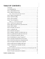
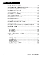
Страница 7: ...PianoDisc Installation Guide 7...

Страница 8: ...eys down while pulling out the action The slightest pressure on a key will lift its hammer thereby causing the hammer to catch on the pinblock and may cause damage when the action is pulled out of the...

Страница 9: ...Pianos with leg bolts sometimes present a problem when attempting access to all 88 keys It may be necessary to omit some key solenoids on both ends of the keyboard due to the interference of the leg b...

Страница 10: ...keyboard is Group 2 Moving to the right is the low treble area Group 3 Group 4 is the high treble area at the right end of the keyboard with the smallest hammers The small open spaces between these g...

Страница 11: ...PianoDisc Installation Guide 11 E Do the same for the tenor and treble sections F Label each rail Bass Tenor Treble Figure 2A...

Страница 12: ...12 PianoDisc Installation Guide 228CFX PianoCD iQ Step 2 Measure for the key groups continued Figure 2B Figure 2C...

Страница 13: ...in each section i e 1 and 28 Measure 3 4 19 mm toward the front of the key and mark the point on the keyframe felt With a straight edge draw a line in each section connecting the points marked on the...

Страница 14: ...e then no additional support is necessary Continue to Step 5 B Shimming the keyframe If shimming is necessary you must locate where to place the shim and how thick the shim must be Looking at Figure 4...

Страница 15: ...saw cut away the keyframe in the marked area conforming to the line drawn in the previous step Remove the sawdust with a vacuum or a blower CAUTION Do not cut away the supports for the action bracket...

Страница 16: ...Step 7 Transfer your measurements A Remove the keyframe from the piano B Transfer the keyframe cut outline from the top inside to the bottom outside of the keybed where you will have access to it with...

Страница 17: ...easure 2 51 mm to the right of line B which establishes the back of the slot line C C Using the 1 8 3mm holes drilled in step 7C looking inside the piano measure from 1 8 3 mm hole to end of slot insi...

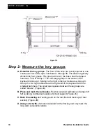
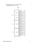
Страница 18: ...18 PianoDisc Installation Guide 228CFX PianoCD iQ Figure 7A...

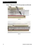
Страница 19: ...PianoDisc Installation Guide 19 Figure 7B...

Страница 20: ...ake sure that the saw blade has enough clearance B Check the depth of the saw blade Make sure not to cut accidentally into the damper tray C Remove the dags It is very likely that the piano you are re...

Страница 21: ...lines B and C It is easier to cut long straight lines with a circular saw than with a jig saw B Cut the ends of the slot Make the two short end cuts along the lines that you drew in Step 8 Make these...

Страница 22: ...t to match the length of the slot Drill screw holes in the angle iron at 6 153 mm intervals or into each plank so that it can be secured to the bottom of the keybed Also use a countersink bit on the h...

Страница 23: ...of the rail cover so interference with the solenoids or wiring is minimal B Position the rail cover onto the piano leaving 1 8 3 mm spacing at each end of slot at A and B see Fig 10 Position side C of...

Страница 24: ...nt legs bass and treble locations on the piano B Place a mark on the legs where the rail cover intersects Allow 1 8 3 mm clearance between the leg and rail cover For pianos with an interlock leg such...

Страница 25: ...corda lever B Measure the distance from the back edge of the una corda lever to the edge of the solenoid slot See Figure 13 If this distance is 3 4 19 mm or more there is adequate room to install the...

Страница 26: ...position of the mounting screws with a pencil and then drill the pilot holes for the lyre support When drilling these holes be sure not to drill all the way through the keybed Now re attach the keybe...

Страница 27: ...aside B Attach the mounting bracket to the solenoid assembly Remove the two bolts that attach the solenoid to the bracket use a 7 16 12 mm wrench for this Now place the mounting bracket onto the solen...

Страница 28: ...metimes less than a thousandth of an inch There is very little room for error A Place the lyre back into its position on the piano B Drill a hole through the sustain lever Using the diagram in figure...

Страница 29: ...case it is necessary to install a beam of wood to mount the sustain solenoid and possibly a speaker Use a 4 x 6 piece of wood attached by metal L brackets on the belly rail At the other end use glue...

Страница 30: ...s and the damper tray up to the damper leavers Now mark the threaded rod to be cut off flush with the bottom of the sustain lever At the same time mark the location where threaded rod hole will be dri...

Страница 31: ...hich type of sostenuto is on the piano and follow the instruction appropriate for your situation A Mark ball linkage location Locate the sostenuto connection at the bass tenor break Place a 90 degree...

Страница 32: ...32 PianoDisc Installation Guide 228CFX PianoCD iQ...

Страница 33: ...end at the top Place the other end of the spring as close to the ball linkage as possible You should be within 1 2 13 mm of the ball linkage Make a mark at the top end of the torsion spring on the key...

Страница 34: ...die thread 1 26 mm of the rod Then use the correct size of drill bit screw in fit to drill the dowel Use super glue on the rods during assembly In example B it is necessary to drill out the end of the...

Страница 35: ...od At the mark made in step 20 N trim off the excess length from the threaded rod Clean off burr from threaded rod on the belt sander or with a file Q Glue felts and grommet to trapwork R Paint the tr...

Страница 36: ...er the sostenuto rod parallel to the solenoid slot and mark the location for the mounting the ball linkage B Pivot bracket location Measure from the sostenoto pedal rod to the ball linkage line on the...

Страница 37: ...is typical in conventional sostenuto trapwork and consequently is probably already available from the trapwork of the piano you are working on presently In fact since most pianos have the push type s...

Страница 38: ...lever 2 on the line at the bass tenor break This is the ball linkage line established in step 21 A Then Position lever 2 so it will mount outside of the rail cover area Attach the lever with the screw...

Страница 39: ...e the connection point of the threaded rod to the sostenuto lever As the illustration above indicates the threaded rod should be at an exact right angle to keybed Determine the place on the lever wher...

Страница 40: ...se we cut a solenoid slot in the keybed we lose the guide hole for the Steinway sostenuto This is not a problem as we have a perfect solution A The bass section on all Steinway pianos have an even num...

Страница 41: ...y drilled hole in the plunger Notice it acts like a ball and socket giving some flexibility See Fig 23 F Insert the threaded rod into top of guide solenoid See Fig 23 with the plunger and you will not...

Страница 42: ...42 PianoDisc Installation Guide 228CFX PianoCD iQ Figure 24 Solenoid is used as a guide for Steinway sostenuto Figure 25 Steinway Sostenuto...

Страница 43: ...PianoDisc Installation Guide 43 Secure spring attachment on monkey with veneer glued to the sides or small piece of metal soldered to the spring as shown above Figure 26...

Страница 44: ...in the location outlined C Place the sustain and the sostenuto trapwork back on the piano Next place the lyre on the piano D Looking through the drilled pitman holes of the 2 levers place a mark on th...

Страница 45: ...der with a barrel sander to remove the sharp edge See Figure 28 B Install the two black rubber grommets into the 1 25 mm access holes C Place the plastic plugs in the rail cover if record is not insta...

Страница 46: ...id firmly and place a 6x32x3 8 10mm screw in solenoid mounting slot Install the appropriate number of long stem solenoids on the rail NOTE Make sure the stems line up exactly to the lines C Remove the...

Страница 47: ...ble sections I Attaching the bracket to the rail requires two 10x1 2 13 mm hex headed screws per bracket which are provided in the kit Each bracket and rail position has three sets of mounting holes D...

Страница 48: ...that the mounting screws are approximately in the middle of the slot This leaves room for a small final adjustment Mount two brackets on each rail Figure 32 Step 25 Install the solenoid rail A PianoD...

Страница 49: ...m each stud Place the solenoid rail on the two studs adjusting the nuts so that the rubber tips of the plungers barely touch the bottom of the keys Replace the remaining jam nuts to hold the rail in p...

Страница 50: ...bed behind the solenoids using 6 x 5 8 screws See Fig 34 The bass tenor boards face the back of the piano The treble board is mounted flat onto the keybed The tenor and bass driver mount vertically No...

Страница 51: ...other plugs into J1 of the tenor board B Connecting the driver harness cable The gray cable has a 2 pin plug and 3 equally spaced 4 pin plugs Plug the 2 pin plug into the CPU Starting at the Bass plug...

Страница 52: ...52 PianoDisc Installation Guide 228CFX PianoCD iQ Figure 35...

Страница 53: ...using the mounting hardware provided Attach the power supply to a beam or inner rim Keep the heat sink side down The voltage adjustment screw is on the top side of the power supply Prior to securing...

Страница 54: ...nough to clear the rail cover Three inch square blocks of plywood of proper thickness will work well Paint the blocks to match the bottom of the piano and secure with wood glue and screws Discarded ke...

Страница 55: ...ims to the bottom of the key rest felt Step 32 Action regulation procedure The PianoDisc system will perform optimally when the piano action is operating at the manufacturer s specifications The follo...

Страница 56: ...ey solenoid rail adjustment NOTE Before raising the solenoid rails to their final position check the hammer line and make any necessary adjustments A The proper height of the rails is achieved when th...

Страница 57: ...noDisc Installation Guide 57 Figure 39 C Look across the bottom of all three solenoid rails for a quick check to see the level of accuracy of the height adjustment All three rails should line up strai...

Страница 58: ...iQ control units See Appendix A Mounting and Installing iQ Systems NOTE If the control unit is located over 50 feet from the piano a 3 amp wall transformer must be used These are available from PianoD...

Страница 59: ...the control box E Press test button located on the C P U interface See Fig 41 This will start the playing of the solenoids from the Bass to the Treble end If the solenoids fail to play disconnect the...

Страница 60: ...casionally as a result of either a poor regulation or worn parts the solenoid stroke must be adjusted to a longer distance than is desirable Keep in mind however that the longer the stroke the more he...

Страница 61: ...d rod Figure 43 B Sustain pedal solenoid adjustment Insert the test disk into the control box select damper test song 2 and press play Song repeat can also be selected for continual repeat Observe the...

Страница 62: ...62 PianoDisc Installation Guide 228CFX PianoCD iQ...

Страница 63: ...oid ensure that jam nuts are tight D Mount the rail cover as explained in Step 13B The CPU driver cover must be secured to the rail cover Attach the rail cover to the CPU driver cover with the screws...

Страница 64: ...64 PianoDisc Installation Guide 228CFX PianoCD iQ...

Страница 65: ...stalling an iQ system is a simple procedure To complete installation you need to A Securely mount the iQ control box to the piano B Connect the iQ control box to the CPU audio speakers and music playe...

Страница 66: ...by connecting the iQ control box to the CPU audio speakers and music player e g iPod MP3 player multi media player etc After all cable connections are complete secure and store the cables To connect t...

Страница 67: ...use secure and store all remaining cable length with Velcro straps To secure and store excess cable length 1 Remove two 1 x 4 Velcro cable straps from the Installation Kit 2 Staple the Velcro cable s...

Страница 68: ...68 PianoDisc Installation Guide 228CFX PianoCD iQ...

Страница 69: ...ecessary amount of power required to strike and hold the pedal properly Level Adjust Mode use this system mode to match or balance iQ s internal volume level with the volume level of the music player...

Страница 70: ...ns amber A Learn table was found The system is ready for configuration or music playback For Wireless Systems Status LED illuminates red Select LEDs illuminate yellow for one second Status LED remains...

Страница 71: ...scroll to key 1 Moving up from key 88 rolls over to key 1 Push in and release the Select wheel The Learn LED starts double flashing Key 1 is playing and ready for adjustment NOTE PianoDisc recommends...

Страница 72: ...not repeat steps 1 4 to further adjust the keys NOTE Rapidly playing the keys let s you listen for volume level consistency from key to key 6 Save the Learn settings Push in and hold the Select wheel...

Страница 73: ...Learn LED flashes steadily After two seconds the Status LED illuminates green 3 Release the Select wheel The pedal starts to rise and fall The initial pedal hold value is 0 and strike value is 50 4 Yo...

Страница 74: ...ike by increments of 5 2 If satisfied with the pedal adjustments push in and release the Select wheel to save your adjustments and exit the Pedal Adjust mode You ll see a dark Learn LED and an illumin...

Страница 75: ...t varies between media player types and brands starting your adjustment between mid and maximum volume gives you a wide enough range high or low to find the optimal playback level for your system and...

Страница 76: ...the volume levels While the LEDs sync level and learn are flashing iQ is matching its internal piano and accompaniment volumes to the media player s volume levels 5 When iQ finishes matching its inte...

Страница 77: ...he Sync mode 2 Rotate the Select wheel to Hold the wheel in this position to decrease synchronization in a slow continuous movement Rotate and release the wheel to decrease the sync by five millisecon...

Страница 78: ...iQ system to use previously saved volume level match settings Exiting the Learn mode to discard changes made to the Learn table causes the iQ system to use previously saved Learn table values NOTE Exi...

Страница 79: ...to press and hold the Reset button until the LED lights blink 3 Release the button and the Status LED is illuminated to indicate normal operation and restoration of default values If in Sync Adjust m...

Страница 80: ...the Sync LED begins to blink The Sync LED continues blinking and the Status LED remains lit until the system clears all Sync Level and Learn values When the Sync LED stops blinking iQ has returned to...

Страница 81: ...till holding the Reset button The Status LED turns green 3 Release the Reset button The Learn LED starts flashing 4 Rotate the Select wheel Then push in and release Auto detection is turned off and th...

Страница 82: ...the left of the decimal point is represented i e 1 2 An illuminated LED 1 A dark LED 0 3 Release the Select wheel The number to the right of the decimal point is represented i e 1 2 The display lasts...

Страница 83: ...to MIDI cable that comes with the iQ wireless option connect the MIDI Out port on the iQ control box to the MIDI In port on the wireless transmitter See www audio technica com for more information abo...

Страница 84: ...84 PianoDisc Installation Guide 228CFX PianoCD iQ...

Отзывы: