


User Manual
E727T0005, valid for E-727
BRO, 2019-06-28
Physik Instrumente (PI) GmbH & Co. KG, Auf der Roemerstrasse 1, 76228 Karlsruhe, Germany
Page 34 / 240
Phone +49 721 4846-0, Fax +49 721 4846-1019, Email
Output Generation
Multiple piezo actuators can be used to execute the motion of an axis, i.e. multiple output signal
channels (piezo amplifiers) can be involved. The control value for an axis is transformed to control
voltage values for the output channels via the output matrix. After the digital-to-analog
conversion, the resulting control voltage values are sent to the piezo amplifiers whose output
drives the actuators in the mechanics.
With E-727.xxxA and .xxxAx models, the control voltage values can also be output by the analog
output line to control an external amplifier (see "Using the Analog Output" (p. 94) for more
information).
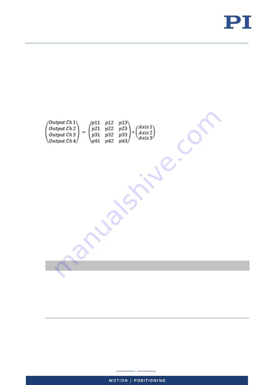
Output matrix of the E-727:
In equation form:
OutputCh
1
= p
11
Axis
1
+ p
12
Axis
2
+ p
13
Axis
3
OutputCh
2
= p
21
Axis
1
+ p
22
Axis
2
+ p
23
Axis
3
OutputCh
3
= p
31
Axis
1
+ p
32
Axis
2
+ p
33
Axis
3
OutputCh
4
= p
41
Axis
1
+ p
42
Axis
2
+ p
43
Axis
3
The matrix coefficients are given by the following parameters (with i = 1 to 3, or 1 to 4, depending
on the number of axes provided by the E-727, i.e. each parameter has a different value for each of
the logical axes):
p
1i
=
Driving Factor of Piezo 1
, parameter ID 0x09000000,
p
2i
=
Driving Factor of Piezo 2
, parameter ID 0x09000001,
p
3i
=
Driving Factor of Piezo 3
, parameter ID 0x09000002
P
4i
=
Driving Factor of Piezo 4
, parameter ID 0x09000003
In PIMikroMove, these parameters are available in the
Axis Definition
parameter groups in the
Device Parameter Configuration
window. In addition, you can check the matrix coefficients in the
Axis Matrices
window (open via
View -> Axis Matrices
menu item of the
Device Parameter
Configuration
window).
INFORMATION
During calibration at the factory, the coefficients of the output matrix are set numerically to the
number of volts which are required per axis unit by the attached piezo actuators (i.e. the unit of
the coefficients is V/µm). Thus both the closed-loop control value and the open-loop control value
correspond numerically to axis position values. This means that all control sources always
command with axis position values, irrespective of the current operating mode. You should not
change the coefficients for the piezo amplifier channels.
If the connected mechanics has an ID-chip, the coefficients will be read in from the ID-chip (see
"ID-Chip Support / Stage Replacement" (p. 131) for more information).
The VOL? command reports the current voltage output of the output signal channel (in volts).