background image

16

NEOX™ Tilt-in-Space

ENGLISH

6.3   Quick release axle (Optional)

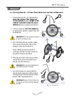
Follow these steps to uninstall quick release: 

1.  Release the wheel lock by pulling it backward;

2.  Completely depress quick-release button 

A

;

3.  Remove the wheel while keeping the button 

A

 pushed in.

When you re-install the quick release axle, ensure that both quick-release 

rear axles are locked. An unlocked axle may come off during use and 

cause a fall.

Always use the more stable position (Wheel Backward) to guaranty 

stability. To propel, consider the 6 wheel configuration. 

Figure 13 : Quick Release Use

Insert fully lock 

pin

6.4   Adjusting the Wheelbase forward and back

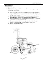
The mid wheel drives’ position is very 

important for the base stability. The more the 

mid wheel drives are positioned forward, the 

more the stability is decreased. However, it 

facilitates propelling. To satisfy the need of 

each individual it is possible to proceed to 

different horizontal adjustments.

Follow these steps:

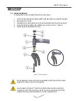
1.  Remove the rear wheel (refer to section 7);

2.  Unscrew screw 

A

 and 

B

 using 13 mm Allen 

Key; 

3.  Slip the anchoring plate to obtain the 

desired position;

4.  Replace screw 

A

 and 

B

, tighten.

Figure 14 : Adjusting the Wheelbase forward 

and back

A

B


Содержание NEOX Tilt-in-Space

Страница 1: ...Owners Manual This manual contains important information about this product Please pass it to the final user upon delivery...

Страница 2: ...rom a lack of care or misuse or from any modification made to the product without prior written consent of the company For Physipro Inc your satisfaction remains a priority Table of contents 1 NEOX Pa...

Страница 3: ...3 11 4 Depth adjustable footplates 33 11 5 Folding footplate 34 12 Elevating and articulating legrest 34 12 1 Installation 34 12 2 Height adjustment 35 12 3 Angle adjustment 35 13 Wheel lock 36 13 1 W...

Страница 4: ...rovided with the standard model Several options and accessories are also available Please contact us for more details or refer to the purchase order Figure 1 Wheelchair Main Components Armrest Footpla...

Страница 5: ...4 wheels 50 8 lb Neox 6 wheels 55 8 lb J Maximum load 250 lb 350 lb Back angle 85 to 115 5 increments Gas recline back max 130 Tilt 5 to 45 Armrest U Type 7 to 12 U Type lowered 6 to 9 Footrest 60 70...

Страница 6: ...ure that the wheelchair rolls straight and that all parts work smoothly Check for noise vibration or a change in ease of use Make sure that the wheel locks do not interfere with tires when rolling Ver...

Страница 7: ...hair without any assistance Never use the footplate as a platform When getting in or out of the wheelchair make sure that the footplates are in the upward position Do not stand on the frame of the whe...

Страница 8: ...lean back and let the handrims slide slowly in your hands You should always be able to stop the wheelchair by blocking the handrims Note Always have an assistant behind the wheelchair when going down...

Страница 9: ...p Avoid excess moisture Weight Limitation NEVER exceed the weight limit for combined weight of user and items carried Exceeding the weight limit may result in injury or damage to your chair a fall tip...

Страница 10: ...If the user is contagious disinfect the seat the armrests the backrests and every other surface daily with a disinfectant Do not rinse or wipe just let it dry 3 3 3 Storage Store your chair in a clean...

Страница 11: ...ackward or forward to get the desired depth 4 Replace sleeves bolts and armrest hardware tighten Warning Do not over tighten bolts A to avoid blocking the armrest hardware pivot It is also necessary t...

Страница 12: ...llow these steps to modify the width 1 Using a 3 mm and 8 mm Allen key unscrew bolt A remove the rigidizer B if needed 2 Using two 10 mm Allen Keys unscrew bolt D and using two 13 mm Allen Keys unscre...

Страница 13: ...ng can cause serious injury to the user or others Position Casters Limited tilt in space with a seat to floor height of 13 and 14 Position Rear Wheel 4 wheel configuration Rear wheel Front wheel Posit...

Страница 14: ...ed Location P1 P2 20 14 to 19 X 22 14 to 19 X 24 15 to 20 X Self propelling configuration Please note that the central wheels are the only wheels that have to be chosen in function of the seat to floo...

Страница 15: ...t the positioning device B in the hole corresponding to the desired height Figure 12 2 Slide axle A inside the positioning device B 3 Insert nut C at the end of the axle A 4 Tighten nut C with a wrenc...

Страница 16: ...propel consider the 6 wheel configuration Figure 13 Quick Release Use Insert fully lock pin 6 4 Adjusting the Wheelbase forward and back The mid wheel drives position is very important for the base s...

Страница 17: ...ghten nut A to release the positioning device B with the use of a 1 1 8 wrench 3 Unscrew or screw the positioning device B in or out in order to obtain the desired position 4 Firmly tighten nut A with...

Страница 18: ...ported The back wheels will go back to their original position 1 For security reasons it is important to HAVE THE UPHOLSTERY PARALLEL TO THE GROUND and to REMOVE THE PATIENT S WEIGHT FROM THE BACK WHE...

Страница 19: ...hole with both spacers B between the wheel and fork on each side 3 Put bolt C at the end of screw A and tighten with two 13 mm wrenches This step is required when a front wheel position or seat height...

Страница 20: ...the frame housing C 4 Fasten the fork by tightening nut B using a socket and a wrench 5 Install cap A on the frame housing Figure 19 Caster Installation Ensure tightness when the forks are installed V...

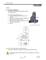
Страница 21: ...Allen key 2 Once the screw has been removed modify the angle to meet your client s needs 3 When the desired angle is reached put screw A in one of the preset holes 4 Tighten Figure 20 Back Angle Modi...

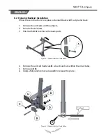
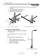
Страница 22: ...1 Remove the armrests and the wheels 2 Remove the backrest 3 Unscrew bolt A to remove the back posts 4 Remove the armrest hardware B screw C and screw H on the small tube 5 Remove bolt D 6 Using a fla...

Страница 23: ...rdware 9 Re install back post and backrest 10 Replace armrest and rear wheels 8 3 Back posts height modification Adjustable or swing away back posts are available in 3 different sizes It can be adjust...

Страница 24: ...27 Recliner Backrest Reclining backpost Figure 26 Recliner Backrest To recline the back simultaneously press handles A located on the reclining back bar and set the back angle Release both handle A to...

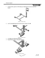
Страница 25: ...J depending on the desired seat depth 2 Insert bushing G H and I inside the holes of plates F and K 3 Complete assembly with hardware 4 Repeat these steps for the right backpost J K I H G F N M L E D...

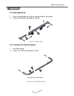
Страница 26: ...the tube P 2 Using a 4 mm Allen Key tighten screw Q 1 Insert R in tube S 2 Using a 3 mm Allen Key tighten screw T O R T S Q P 8 5 Reclining back bar 8 6 Tension bar for headrest support Backpost Left...

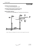
Страница 27: ...crews U Installation of the tension bar for headrest support 2 Using a 4 mm Allen Key tighten screws V Recline handles installation 3 Install the recline handle W using a 1 8 Allen Key to screw in X s...

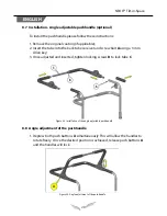
Страница 28: ...er and screw bolt A using a 3 mm Allen key 3 Once adjusted and inserted tighten locking screws B to lock tube C Figure 34 Installation of the angle adjustable pushhandle 8 8 Angle adjustment of the pu...

Страница 29: ...2 Tilt the NEOX by simultaneously pressing the 2 handles A 3 Release the handles to the desired tilt 4 If needed the maximum positive tilt can be limited by a locking collar C installed on the interio...

Страница 30: ...ar wheels position 2 By default the upright position is 0 To obtain a negative tilt move the adjustment block D and the gas cylinder G forward figure 23 b 3 Position the NEOX in a positive tilt and th...

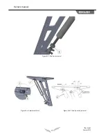
Страница 31: ...31 Revision 3 Janvier 2015 Owners manual ENGLISH Figure 38 Tilt in Space control Figure 39 a Adjustment block Figure 39 b Tilt in Space Adjustment Negative tilt...

Страница 32: ...ir 11 1 2 Armrest Height Adjustment 1 Push the release latch B 2 Slide arm pad C up or down to the desired height 3 When the desired height is reached release latch B making sure the armrest is proper...

Страница 33: ...n Figure 42 Footrest Height Adjustment 11 3 Angle Adjustment 1 With a 5 mm Allen key loosen screw A about turn 2 Turn the footplate around the footrest mechanism to adjust the footplate to desired ang...

Страница 34: ...decrease it Figure 44 Footplate Vertical Adjustment Do not lift the wheelchair using its footrests to avoid injuries or damages to your wheelchair Use the rigid parts of the frame 12 Articulated Legr...

Страница 35: ...de the frame tube to the desired height 3 Replace screw A tighten Figure 46 Articulated Legrest Height Adjustment 12 3 Angle adjustment 1 To raise legrest hold the lower part of the footrest while pul...

Страница 36: ...Allen key secure tightly the wheel lock with bolts and nuts A Figure 48 Wheel Lock 13 2 Adjust the tension applied to the wheel by the wheel lock 1 Loosen bolt B using a 4 mm Allen key 2 As needed mo...

Страница 37: ...re that all the nuts are securely fastened after each adjustment 13 4 Attendant Wheel Lock 4 wheel option 1 Adjust A and B according to the frame structure E by inserting them on the tube C 2 Center t...

Страница 38: ...on the side K to release the brakes Figure 53 Apply brakes 4 wheels K J K J 13 6 Attendant Wheel Lock 6 wheel option 1 Unscrew bolts G and nuts H to remove the transit I 2 Adjust A and B according to...

Страница 39: ...re that the wheel lock rods are located at of the wheel when the wheel lock is not applied Figure 55 Attendant Wheel Lock 6 wheels Figure 56 Attendant Wheel Lock 6 wheels F E G I H L 13 7 To Apply Att...

Страница 40: ...r setting To do so press anti tipper release pin B and raise or lower the moving part of the anti tipper Figure 58 Remove and adjust the anti tip Make sure the anti tippers are fully engaged and relea...

Страница 41: ...s complete Make sure the anti tippers are fully engaged and release buttons fully potruding out of adjustment holes Anti tippers must always be used When outdoors on wet soft ground or on gravel surfa...

Страница 42: ...n any other part of the wheelchair Furthermore you have to install the cables as recommended by Transport Canada for maximum security The anchorage rings of the wheelchair do not substitute for the re...

Страница 43: ...nths Front Wheels and Tires Check tire inflation pressure if applicable P P Ensure the fork turns around its axle P P Check if tires are worn P P Ensure the fork and nuts are secured and stable P P Re...

Страница 44: ...armrests are worn P Ensure restraining belts are secured P Cleaning Clean and wax parts P Clean upholstery P 17 Warranty 5 years Frame against defects in materials and workmanship 2 years Parts and la...

Страница 45: ...therein and include the name and address of the supplier the delivery date and the serial number of the product Limitations and Exclusions Thiswarrantyshallnotapplytoproductsthathavebeenalteredorabus...

Страница 46: ...he seat depth according to order form and reference table Adjust the center of mass according to reference table Adjust gas cylinder according to reference table Adjust seat to floor height according...

Страница 47: ...u can use Table 2 as guidelines This was established considering the mass distribution of the ISO 7176 11 2012 standard and a 90 to 95 degree backrest angle Figure 2 Center of mass adjustment Table 2...

Страница 48: ...Tilt recline stability limitation Stability is a main concern for wheelchair Combining tilt and recline may cause instability In order to respect the typical 10 degrees of stability in least stable c...

Страница 49: ...plates that can be installed between the seat frame and the tilting mechanism The purpose of the plates is to have the wheels underneath the armrest compare to outside see Figure 6 and Figure 7 to mi...

Страница 50: ...se interference between the armrest and the wheel This interference will depend on different factor such as wheel diameter seat to floor height armrest position Figure 8 and Figure 9 show a typical in...

Страница 51: ...ence here is some tips Avoid the use of larger diameter wheels especially for lower seat to floor height Keep the seat to floor height as high as possible Have the armrest as high as possible Example...

Страница 52: ...venue Sud Sherbrooke Qu bec J1G 2R7 Canada 1 800 668 2252 info physipro com www physipro com Europe Village des entrepreneurs 461 rue Saint L onard 49000 Angers France 02 41 69 38 01 contact physipro...

Отзывы: