Chapter 1: Installation
33
ON/OFF Switch
The on/off switch connects main power and battery power to the system. In the event that main
power fails, the backup battery system will automatically power the system.
Rear Panel
The rear panel is where the main power cord exits the unit. A 120VAC/60Hz to 8VAC adapter pro-
vides main power to the unit.
Battery Compartment
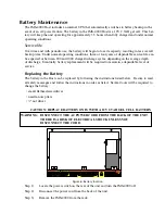
The battery compartment is located below the top panel. The unit requires (1) 6V 3.4AH
rechargeable battery (included). To remove or replace the battery, remove the top cover with a small
flat-head screwdriver. {Note: Earlier versions of the node used six (6) C-size 2000mAHr Ni-Cad
batteries. These units can be identified by their black network jack or via software—they will be
running firmware version 2.xx or earlier.}
Installation
This section provides information on:
n
Operating environment
n
Rack, wall, & tabletop installation
n
Connecting sensors
n
Replacing batteries
Parts Required
Phillips
DB9 F/F null
Dumb terminal or PC
Screwdriver
modem cable
w/DB9 serial port
Operating Environment
Before you install the IMS-4000 Node be sure that your operating environment meets the physical
requirements of the equipment.
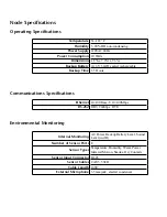
Operating Temperature: 32º–122º Fahrenheit (0º–50º C)
Humidity:
5–90 %RH, non-condensing
Power:
120VAC 60 Hz outlet within 6'
Rack Requirements:
Standard 19' equipment rack with supplied mounting bracket
hardware. Requires 1.0 EIA rack mount space.
Tabletop requirements: Flat area which can support an enclosure 10" wide by 8" deep by
2" high.
Содержание Sensaphone IMS-4000
Страница 1: ...IMS 4000 User s Manual Version 2 4 8 PHONETICS INC SENSAPHONE ...
Страница 44: ......
Страница 59: ......
Страница 60: ......
Страница 102: ......
Страница 106: ...IMS 4000 Manual 106 ...
Страница 135: ...Chapter 7 IMS 4000 Sensors 135 ...
Страница 146: ...IMS 4000 Manual 146 ...
Страница 148: ...IMS 4000 Manual 148 ...
Страница 158: ...IMS 4000 Manual 158 ...
Страница 159: ...159 ...
Страница 160: ...IMS 4000 Host Installation Manual 160 ...

