

42
5756B
INTERBUS System Operation From
the PLC
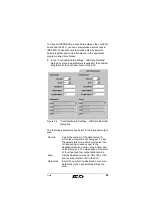
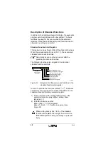
The controller board has a standard register set for
diagnostics and for basic control of the bus system. The
registers are mapped in input and output memory areas of the
PLC depending on the base address of the controller board.
You can read from or write to the registers using direct I/O
commands.
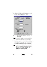
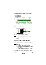
In STEP 7
®
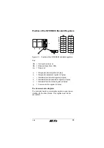
and IBS CMD, the base address must be
set according to the slot of the board in the S7 system
(see Figure 29 on page 43 and "Possible Slots" on
page 10.
If a type of CPU that enables the base address to be
changed manually in STEP 7
®
is being used, this
address can also be set in IBS CMD.
The standard registers can be addressed either directly
through load or transfer instructions, or through a driver block.
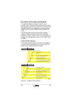
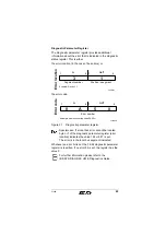
The standard register set consists of three diagnostic
registers:
–
Diagnostic status register (input word)
–
Diagnostic parameter register (input word)
–
Expanded diagnostic parameter register (input word)
Three standard function registers:
–
Standard function start register (input/output word)
–
Standard function parameter register (input/output
word)
–
Standard function status register (input word)


