IL PB BK DI8 DO4/EF-PAC
4-4
PHOENIX CONTACT
7725_en_01
4.2
Principle of dynamic configuration
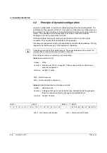
In dynamic configuration, a maximum configuration is specified during configuration. The
addresses are thus reserved in the PLC. Any subgroup of this maximum configuration can
be operated. This type of subgroup can be selected and activated during configuration and
runtime. The advantage is that the application can divide an identical hardware
configuration into active and inactive terminals.
Optional terminals that are only required for additional functions do not have to be
connected. They can simply be deactivated by the application.
If a subsequent extension is planned, the application can activate the new devices. The only
requirement is that they are part of the maximum configuration.
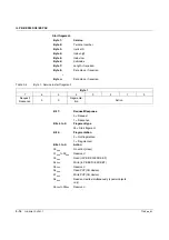
Three indices on the bus coupler are used for handling:
Index 4:
General control bits
Index 6:
Activation/deactivation of devices and slots
All settings are stored in the volatile memory. Thus easy replacement is ensured. The
terminal does not have to be parameterized in advance.
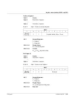
Access:
Write
Function:
Details under "Slot 0" on page B-1. Please observe bit 0 and bit 3 during
dynamic configuration.
Structure
:
Length of 1 bytes
Bit 0:
Restart local bus
Bit 3:
Unlock dynamic configuration
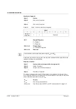
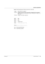
Access:
Read and write
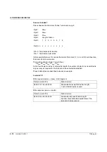
Function:
Indicates which devices are active/inactive. Deactivation via the parameter
telegram (reservation of empty spaces) is also indicated here.
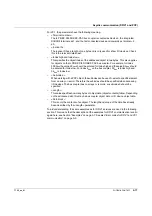
Structure
:
Length of 8 bytes
Byte 1
Byte 2
Bytes 3 ... 7
Byte 8
1
2
3
4
5
6
7
8
9
10
11
12
13
14
15
16
...
57
58
59
60
61
62
63
x
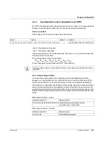
Bit = 0: Terminal and slot inactive
Bit = 1: Terminal and slot active
Содержание IL PB BK DI8 DO4/EF-PAC
Страница 2: ......
Страница 24: ...IL PB BK DI8 DO4 EF PAC 2 14 PHOENIX CONTACT 7725_en_01 ...
Страница 62: ...IL PB BK DI8 DO4 EF PAC 5 2 PHOENIX CONTACT 7725_en_01 ...
Страница 64: ...IL PB BK DI8 DO4 EF PAC 6 2 PHOENIX CONTACT 7725_en_01 ...
Страница 72: ...IL PB BK DI8 DO4 EF PAC A 8 PHOENIX CONTACT 7725_en_01 ...

