


AXL SE PSDI8/3
38 / 84
PHOENIX CONTACT
108928_en_02
6.2
Parameterization of the safe inputs
The individual input pairs of a Smart Element can be parameterized differently, which means
that different safety integrity levels (SIL, SILCL, Cat., PL) can be achieved.
The safe inputs are parameterized in pairs.
describes the parameterization
options.
Table 6
-
1
Parameterization of each input pair
Parameterization
Value range
Comment
Assignment
–
Both not used
– Used, 1-channel both
– Used, 2-channel equivalent
– Used, 2-channel non-equiva
-
lent
Parameterize the input pairs in pairs.
In 2-channel operation, the inputs have a fixed assignment
to one another:
See
“Two-channel equivalent assignment” on page 39
and
“Two-channel non-equivalent assignment” on page 41
The input information of inputs parameterized for 2-channel
operation is mapped to one bit. The unused bits are always
set to “0”.
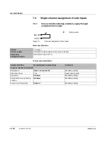
In 1-channel operation, the inputs can operate inde
-
pendently of one another.
See
“Single-channel assignment” on page 39
.
Filter time (t
Filter
)
– 1.5 ms
–
3 ms
– 5 ms
– 15 ms
The filter time is used to suppress interference for the input
signals.
Select the filter time so that the duration of the input signal is
greater than the filter time.
WARNING:
The filter time affects the response time of
the safety function.
See
“Processing time of the input in the event of a safety
Symmetry
–
Disabled
– 100 ms
– 1 s
– 5 s
Parameterization is only to be applied, if the input pair is
parameterized for 2-channel operation.
See
“Symmetry and start inhibit” on page 42
Start inhibit due to
symmetry violation
–
Disabled
– Enabled
Disabled: only a diagnostic message is generated in the
event of symmetry violation.
Enabled: a diagnostic message is generated in the event of
symmetry violation. In addition, the affected input pair is set
to the safe state.
See
“Symmetry and start inhibit” on page 42
Cross-circuit monitor
-
ing
– Disabled
–
Enabled
As soon as cross-circuit monitoring is enabled for an
assigned input pair, clock outputs OUT_T1 and OUT_T2 are
clocked. Otherwise, the clock outputs are enabled without
clocking.
See
“Cross-circuit detection” on page 44
The default values are shown in
bold
.