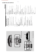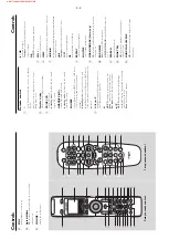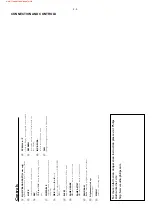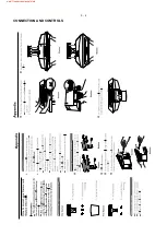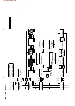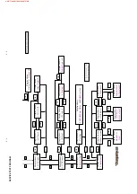
5 - 2
5 - 2
SER
VICE TEST PROGRAM
STOP
VOL
VOL
Display shows
0.Information
Display shows
9.Reset Setting
Display shows
6.LCDContrast
Display shows
5.FANControl
OK
Display shows
0.1ModVersion
Display shows
0.2WiFiMAC
Display shows
0.3EtherMAC
Display shows
ModuleVer
2194*
OK
OK
VOL
VOL
Display shows
WiFi MAC
012345678901*
STOP
Display shows
Ethernet MAC
012345678901*
OK
STOP
STOP
OK
Display shows
Setting OK
or
Setting Fail
Display shows
5.1Full Speed
Display shows
5.2FAN Off
VOL
VOL
OK
STOP
Display shows
Setting Deployed
OK
Display shows
6.1Setting1
Display shows
6.2Setting2
VOL
VOL
OK
STOP
OK
Display shows
6.3Setting3
Display shows
Setting Deployed
VOL
VOL
Display shows
Resetting
OK
Display shows
EEPROMReset OK
or
EEPROMReset Fail
STOP
www.freeservicemanuals.info
Содержание Streamium WACS7000
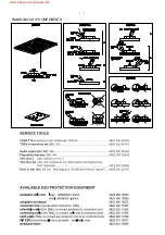
Страница 3: ...1 1 HANDLING CHIP COMPONENTS www freeservicemanuals info ...
Страница 4: ...1 2 www freeservicemanuals info ...
Страница 9: ...3 4 CONNECTION AND CONTROLS www freeservicemanuals info ...
Страница 19: ...6 1 6 1 SET BLOCK DIAGRAM waC7000 www freeservicemanuals info ...
Страница 20: ... 14V 6 2 6 2 SET BLOCK DIAGRAM waS7000 www freeservicemanuals info ...
Страница 21: ...7 1 7 1 SET WIRING DIAGRAM waC7000 www freeservicemanuals info ...
Страница 24: ...8 2 8 2 KEYS RC BOARD Layout Diagram waC7000 SIDE A SIDE B www freeservicemanuals info ...
Страница 29: ...9 4 9 4 PB5 AF BOARD Layout Diagram SideA waC7000 www freeservicemanuals info ...
Страница 30: ...9 5 9 5 PB5 AF BOARD Layout Diagram SideB waC7000 www freeservicemanuals info ...
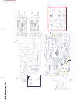
Страница 34: ...11 3 11 3 AMPLIFIER BOARD Layout Diagram side A waC7000 www freeservicemanuals info ...
Страница 35: ...11 4 11 4 AMPLIFIER BOARD Layout Diagram side B waC7000 www freeservicemanuals info ...
Страница 37: ...12 2 12 2 SLOT DVD LOADER CONTROL BOARD Layout Diagram waC7000 SIDE A SIDE B www freeservicemanuals info ...
Страница 39: ...12 4 12 4 PB ATA MS SL Interface Layout Diagram waC7000 SIDE A SIDE B www freeservicemanuals info ...
Страница 41: ...12 4 12 4 PB ATA PW Interface Layout Diagram waC7000 SIDE A SIDE B www freeservicemanuals info ...
Страница 45: ...PB6 KEYS RC Layout Diagram waS7000 14 2 14 2 SIDE A www freeservicemanuals info ...
Страница 46: ...PB6 KEYS RC Layout Diagram waS7000 14 3 14 3 SIDE B www freeservicemanuals info ...
Страница 51: ...PB5 AF BOARD Layout Diagram waS7000 15 5 15 5 SIDE A www freeservicemanuals info ...
Страница 52: ...PB5 AF BOARD Layout Diagram waS7000 15 6 15 6 SIDE B www freeservicemanuals info ...
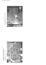
Страница 64: ...16 12 16 12 LAYOUT DIAGRAM side A www freeservicemanuals info ...
Страница 65: ...16 13 16 13 LAYOUT DIAGRAM side B www freeservicemanuals info ...
Страница 70: ...REVISION LIST 18 1 Version 1 0 3141 785 31350 Draft release www freeservicemanuals info ...

