background image

DATA  SHEET

Product specification
Supersedes data of 1996 Jan 09
File under Integrated Circuits, IC01

1998 Feb 16

INTEGRATED CIRCUITS

SAA7345
CMOS digital decoding IC with
RAM for Compact Disc

Содержание SAA7345

Страница 1: ...DATA SHEET Product specification Supersedes data of 1996 Jan 09 File under Integrated Circuits IC01 1998 Feb 16 INTEGRATED CIRCUITS SAA7345 CMOS digital decoding IC with RAM for Compact Disc ...

Страница 2: ...al to Analog Converter DAC deactivation during digital silence Double speed mode Compact Disc Read Only Memory CD ROM modes A single speed only version is available SAA7345GP SS GENERAL DESCRIPTION The SAA7345 incorporates the CD signal processing functions of decoding and digital filtering The device is equipped with on board SRAM and includes additional features to reduce the processing required...

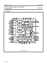
Страница 3: ...REF V DDA SAA7345 MOTO1 CRIN VDD1 VSS1 CL16 MISC DATA SCLK WCLK VSSA VDD2 VSS2 CROUT DIGITAL PLL EBU INTER FACE AUDIO PROCESSOR FLAGS ERROR CORRECTOR MOTOR CONTROL Q CHANNEL CRC CHECK Q CHANNEL REGISTER RAM ADDRESSER SRAM EFM DEMODULATOR VERSATILE PINS INTERFACE PEAK DETECT KILL SERIAL DATA INTER FACE SUBCODE MICRO CONTROLLER INTERFACE TIMING PLL FRONT END 8 9 7 10 6 5 13 14 1 29 17 31 30 32 28 3 ...

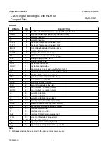
Страница 4: ...put CROUT 14 crystal resonator output VDD1 15 digital supply to input and output buffers note 1 VSS1 16 digital ground to input and output buffers note 1 CL16 17 16 9344 MHz system clock output MISC 18 general purpose DAC output 3 state DATA 19 serial data output 3 state WCLK 20 word clock output 3 state SCLK 21 serial bit clock output 3 state MOTO1 22 motor output 1 versatile 3 state MOTO2 23 mot...

Страница 5: ... 2 3 4 5 6 7 8 9 10 11 33 32 31 30 29 28 27 26 25 24 23 12 13 14 15 16 17 18 19 20 21 22 44 43 42 41 40 39 38 37 36 35 34 CFLG RAB CL DA CLA PORE KILL V3 V4 V5 MOTO2 CL11 IREF DOBM V1 V2 TEST2 TEST1 ISLICE HFIN HFREF V DDA SAA7345 MOTO1 CRIN CROUT V DD1 V SS1 CL16 MISC DATA SCLK WCLK V SSA V DD2 V SS2 Pins 34 to 42 inclusive have no internal connection ...

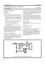
Страница 6: ...internal current source applied to an external capacitor under the control of the digital phase locked loop DPLL Regeneration of the bit clock is achieved with an internal fully digital PLL No external components are required and the bit clock is not output The PLL has two microcontroller control registers addresses 1000 and 1001 for bandwidth and equalization For certain applications an off track...

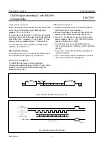
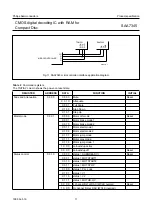
Страница 7: ...s shown in Table 2 These can be written to via the microcontroller interface using the protocol shown in Fig 5 Write operation sequence RAB is held LOW by the microcontroller to hold the SAA7345 DA pin at high impedance Microcontroller data is clocked into the internal shift register on the LOW to HIGH clock transition CL Data D 3 0 is latched into the appropriate control register address bits A 3...

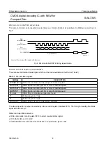
Страница 8: ...propriate data to register 0010 to select required status signal With RAB LOW set CL LOW Set RAB HIGH this will instruct the SAA7345 to output status signal on DA SIGNAL DESCRIPTION SUBQREADY I LOW if new subcode word is ready in Q channel register MOTSTART1 HIGH if motor is turning at 75 or more of nominal speed MOTSTART2 HIGH if motor is turning at 50 or more of nominal speed MOTSTOP HIGH if mot...

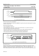
Страница 9: ...de bits after each HIGH to LOW transition of CL When enough subcode has been read 1 to 96 bits stop reading by pulling RAB LOW PEAK DETECTOR OUTPUT In place of the CRC bits bits 81 to 96 the peak detector information is added to the Q channel data The peak information corresponds to the highest audio level absolute value and is measured on positive peaks Only the most significant 8 bits of the pea...

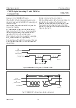
Страница 10: ...that t3 will be below 26 2 ms approximately If subcode frames with failed CRCs are present the t2 and t3 times will be increased by 13 1 ms for each defective subcode frame SHARING THE MICROCONTROLLER INTERFACE When the RAB pin is held LOW by the microcontroller it is permitted to put any signal on the DA and CL lines SAA7345 will set output DA to high impedance Under this circumstance these lines...

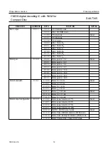
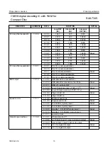
Страница 11: ... brake mode 2 X 0 1 1 Motor start mode 1 X 1 0 0 Motor start mode 2 X 1 0 1 Motor jump mode X 1 1 1 Motor play mode X 1 1 0 Motor jump mode 1 1 X X X anti windup active 0 X X X anti windup off Reset Status control 0 0 1 0 X 0 0 0 status SUBQREADY I Reset X 0 0 1 status MOTSTART1 X 0 1 0 status MOTSTART2 X 0 1 1 status MOTSTOP X 1 0 0 status PLL Lock X 1 0 1 status V1 X 1 1 0 status V2 X 1 1 1 stat...

Страница 12: ...Motor gain G 8 0 X 1 0 0 Motor gain G 12 8 X 1 0 1 Motor gain G 16 0 X 1 1 0 Motor gain G 25 6 X 1 1 1 Motor gain G 32 0 Motor bandwidth 0 1 0 1 X X 0 0 Motor f4 0 5 Hz Reset X X 0 1 Motor f4 0 7 Hz X X 1 0 Motor f4 1 4 Hz X X 1 1 Motor f4 2 8 Hz 0 0 X X Motor f3 0 85 Hz Reset 0 1 X X Motor f3 1 71 Hz 1 0 X X Motor f3 3 42 Hz Motor output configuration 0 1 1 0 X X 0 0 Motor power maximum 37 Reset ...

Страница 13: ...ion 0 1 0 1 PLL 30 ns under equalization EBU output 1 0 1 0 X X 0 0 EBU data before concealment X X 1 0 EBU data after concealment and fade Reset X X 1 1 EBU off output LOW X 0 X X Level II clock accuracy 1000 10 6 Reset X 1 X X Level III clock accuracy 1000 10 6 0 X X X Flags in EBU off Reset 1 X X X Flags in EBU on Speed control 1 0 1 1 1 X X X double speed mode 0 X X X single speed mode Reset X...

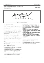
Страница 14: ...o symbols when the error corrector cannot ascertain if the symbols are definitely good C1 generates output flags which are read after de interleaving by C2 to help in the generation of C2 output flags The C2 output flags are used by the interpolator for concealment of non correctable errors They are also output via the EBU signal DOBM and the MISC output with I2S for CD ROM applications The flags ...

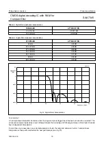
Страница 15: ...way between the preceding and following samples Left and right channels have independent interpolators If more than one consecutive non correctable sample is found the last good sample is held A 1 sample linear interpolation is then performed before the next good sample see Fig 13 PASSBAND ATTENUATION 0 to 19 kHz 0 001 dB 19 to 20 kHz 0 03 dB STOPBAND ATTENUATION 24 kHz 25 dB 24 to 27 kHz 38 dB 27...

Страница 16: ...rnal fade counter The counter is preset to 128 by the Full Scale command if no oversampling is required The counter is preset to 120 0 5 dB scaling by the Full Scale command if either 2fs or 4fs oversampling is programmed in the DAC output register address 0011 The counter is preset to 32 by the Attenuate command The counter is preset to 0 by the Mute command Level counter 128 maximum level To con...

Страница 17: ...POLATION 1 1 0 1 0 fs 16 2 1168 n 1 CD ROM I2S no 2 1 0 1 1 fs 16 2 1168 n 1 CD ROM EIAJ 2 no 3 1 1 1 0 fs 16 2 1168 n 1 Philips I2S 16 bits yes 4 0 0 1 0 fs 16 2 1168 n 1 EIAJ 16 bits yes 5 0 1 1 0 fs 18 2 1168 n 1 EIAJ 18 bits yes 6 0 0 0 X 4fs 16 8 4672 n 1 EIAJ 16 bits yes 7 0 1 0 X 4fs 18 8 4672 n 1 EIAJ 18 bits yes 8 1 1 0 X 4fs 18 8 4672 n 1 Philips I2S 18 bits yes 9 0 0 1 1 2fs 16 4 2336 n...

Страница 18: ...en browsing through the pdf in the Acrobat reader This text is here inThis text is here in white to force landscape pages to be rotated correctly when browsing through the pdf in the Acrobat reader white to force landscape pages to be LEFT CHANNEL DATA WCLK NORMAL POLARITY SCLK 15 15 0 DATA WCLK LSB VALID MSB VALID LSB VALID MSB VALID MISC CD ROM MODE ONLY MGA383 0 Fig 14 Philips I2S data format 1...

Страница 19: ...S FUNCTION Sync 0 to 3 Auxiliary 4 to 7 not used normally zero Error flags 4 CFLG error and interpolation flags when bit 3 of EBU control register is set to logic 1 Audio sample 8 to 27 first 4 bits not used always zero Validity flag 28 valid logic 0 User data 29 used for subcode data Q to W Channel status 30 control bits and category code Parity bit 31 even parity for bits 4 to 30 SYNC The sync w...

Страница 20: ...n detected on both LEFT and RIGHT channels for 200 ms 2 PIN KILL MODE Independent digital silence detection for left and right channels The KILL pin is active LOW when digital silence has been detected in the LEFT channel for 200 ms and V3 is active LOW when digital silence has been detected in the RIGHT channel for 200 ms When MUTE is active then the KILL output is forced LOW Spindle motor contro...

Страница 21: ...l is pulse width modulated on the MOTO2 output Figure 17 shows the timing and Fig 18 a typical application diagram MGA363 1 MOTO2 V DD VSS MOTO1 M 22 kΩ 10 nF 22 kΩ 10 nF VSS VSS MOTO1 M 22 kΩ 10 nF 22 kΩ 22 kΩ VSS VDD VSS 22 kΩ 22 kΩ Fig 16 Motor pulse density application diagrams Fig 17 Motor 2 line PWM mode timing rep t 45 µs t 240 ns dead Accelerate Brake MOTO1 MOTO2 MGA366 MGA365 2 VSS M MOTO...

Страница 22: ... modulated form on the MOTO1 pin carrier frequency 300 Hz and the PLL frequency signal will be put in pulse density modulated form on the MOTO2 pin carrier frequency 4 23 MHz The integrated motor servo is disabled in this mode Remark The PWM signal on MOTO1 corresponds to a total memory space of 20 frames therefore the nominal FIFO position half full will result in a PWM output of 60 Fig 19 Motor ...

Страница 23: ...o the motor No decisions are involved Stop mode 2 The disc is braked as in Stop mode 1 but the PLL will monitor the disc speed As soon as the disc reaches 12 of its nominal speed the MOTSTOP status signal will go HIGH and switch the motor servo to off mode Off mode Motor not steered POWER LIMIT In Start mode 1 Start mode 2 Stop mode 1 and Stop mode 2 a fixed positive or negative voltage is applied...

Страница 24: ...ck input from digital servo X X X 0 input may be read via status register address 0010 data X101 V2 4 input input may be read via status register address 0010 data X110 V3 26 output 1 1 0 0 X X 0 X kill output for right channel X 0 1 X output logic 0 X 1 1 X output logic 1 V4 25 output 1 1 0 1 0 0 0 0 4 line motor drive using V4 and V5 X X 0 1 Q to W subcode output X X 1 0 output logic 0 X X 1 1 o...

Страница 25: ... X X 0 0 no interpolations X X X X X 0 1 at least one 1 sample interpolation X X X X X 1 0 at least one hold and no interpolations X X X X X 1 1 at least one hold and one 1 sample interpolation Fig 22 Flags output timing handbook full pagewidth F1 F2 F3 F4 F5 F6 F7 F1 11 3 µs 45 4 µs MGA370 CFLG ABSOLUTE TIME SYNC The first flag bit F1 is the absolute time sync signal It is the FIFO passed subcode...

Страница 26: ... input voltage 0 5 VDD 0 5 V VO output voltage 0 5 6 5 V IO output current continuous 20 mA Tamb operating ambient temperature 40 85 C Tstg storage temperature 55 125 C Ves1 electrostatic handling note 2 2000 2000 V Ves2 electrostatic handling note 3 200 200 V SYMBOL PARAMETER CONDITIONS MIN TYP MAX UNIT Supply VDD supply voltage 3 4 5 0 5 5 V IDD supply current VDD 5 V 22 50 mA Analog Front End V...

Страница 27: ...ns tf output fall time CL 20 pF note 1 15 ns Digital outputs V4 and V5 VOL LOW level output voltage VDD 4 5 to 5 5 V IOL 10 mA 0 1 0 V VDD 3 4 to 5 5 V IOL 5 mA 0 1 0 V VOH HIGH level output voltage VDD 4 5 to 5 5 V IOH 10 mA VDD 1 VDD V VDD 3 4 V to 5 5 V IOH 5 mA VDD 1 VDD V CL load capacitance 50 pF tr output rise time CL 20 pF note 1 15 ns tf output fall time CL 20 pF note 1 15 ns Open drain o...

Страница 28: ...utput rise time CL 20 pF note 1 10 ns tf output fall time CL 20 pF note 1 10 ns ILI 3 state leakage current VI 0 to VDD 10 10 µA Digital input output DA VIL LOW level input voltage 0 3 0 3VDD V VIH HIGH level input voltage 0 7VDD VDD 0 3 V ILI 3 state leakage current VI 0 to VDD 10 10 µA CI input capacitance 10 pF VOL LOW level output voltage IOL 1 mA 0 0 4 V VOH HIGH level output voltage IOH 1 mA...

Страница 29: ...e fs 95 ns sample rate 2fs 48 ns sample rate 4fs 24 ns th hold time sample rate fs 95 ns sample rate 2fs 48 ns sample rate 4fs 24 ns I2S timing double speed CLOCK OUTPUT SCLK see Fig 23 tcy output clock period sample rate fs 236 2 ns sample rate 2fs 118 1 ns sample rate 4fs 59 1 ns tH clock HIGH time sample rate fs 83 ns sample rate 2fs 42 ns sample rate 4fs 21 ns tL clock LOW time sample rate fs ...

Страница 30: ...ingle speed 480 ns tf fall time double speed 240 ns READ MODE tdRD delay time RAB to DA valid 0 50 ns tdRZ delay time RAB to DA high impedance 0 50 ns tpd propagation delay CL to DA single speed 700 980 ns double speed 340 500 ns WRITE MODE tsuD set up time DA to CL single speed note 2 700 ns double speed note 2 340 ns thD hold time CL to DA single speed 980 ns double speed 500 ns tsuCR set up tim...

Страница 31: ...ming READ mode DA SAA7345 CL RAB t r DD V 0 8 V 0 8 V t r t f t f DD V 0 8 V 0 8 V DD V 0 8 V 0 8 V tpd t L t H t dRD t dRZ high impedance MGA377 1 Fig 25 Microcontroller timing WRITE mode CL RAB t r t f DD V 0 8 V 0 8 V DD V 0 8 V 0 8 V t hD t L t H t dWZ MGA378 1 t r t f DD V 0 8 V 0 8 V t L t H t suCR t suD DA microcontroller high impedance ...

Страница 32: ...345 APPLICATION INFORMATION Fig 26 Application circuits for crystal oscillator 3 3 µH 100 kΩ 1 nF 10 pF 10 pF CRIN CROUT 33 8688 MHz 3rd overtone CRYSTAL 2 2 kΩ 2 2 kΩ 2 2 kΩ 100 kΩ 16 9344 MHz CRYSTAL 100 kΩ 33 pF 33 pF CRIN CROUT 33 8688 CERAMIC GENERATOR 5 pF 5 pF CRIN CROUT MGA360 1 VDDA VSSA VDDA VSSA VDDA VSSA ...

Страница 33: ... CFLG RAB CL DA CLA PORE KILL V3 V4 V5 MOTO2 CL11 IREF DOBM V1 V2 TEST2 TEST1 ISLICE HFIN HFREF V DDA SAA7345 MOTO1 CRIN CROUT V DD1 V SS1 CL16 MISC DATA SCLK WCLK VSSA VDD2 V SS2 12 13 14 15 16 17 18 19 20 21 22 44 43 42 41 40 39 38 37 36 35 34 VDD C7 100 nF C6 4 7 µF 63 V R4 2 2 Ω 16 MHz clock output X9 to DAC MOTOR INTERFACE V C4 100 nF C3 22 nF R3 2 2 kΩ R2 22 kΩ C2 47 pF C1 2 2 nF X6 micro co...

Страница 34: ... 13 9 1 19 2 18 2 2 4 1 8 7 0 o o 0 15 2 35 0 1 0 3 DIMENSIONS mm are the original dimensions Note 1 Plastic or metal protrusions of 0 25 mm maximum per side are not included 2 0 1 2 SOT205 1 95 02 04 97 08 01 D 1 1 1 14 1 13 9 HD 19 2 18 2 E Z 2 4 1 8 D bp e θ E A1 A Lp detail X L A 3 B 11 y c D H bp E H A2 v M B D ZD A ZE e v M A X 1 44 34 33 23 22 12 133E01A pin 1 index w M w M 0 5 10 mm scale ...

Страница 35: ...ng and cooling vary between 50 and 300 seconds depending on heating method Typical reflow peak temperatures range from 215 to 250 C Wave soldering Wave soldering is not recommended for QFP packages This is because of the likelihood of solder bridging due to closely spaced leads and the possibility of incomplete solder penetration in multi lead devices CAUTION Wave soldering is NOT applicable for a...

Страница 36: ... or goal specifications for product development Preliminary specification This data sheet contains preliminary data supplementary data may be published later Product specification This data sheet contains final product specifications Limiting values Limiting values given are in accordance with the Absolute Maximum Rating System IEC 134 Stress above one or more of the limiting values may cause perm...

Страница 37: ...1998 Feb 16 37 Philips Semiconductors Product specification CMOS digital decoding IC with RAM for Compact Disc SAA7345 NOTES ...

Страница 38: ...1998 Feb 16 38 Philips Semiconductors Product specification CMOS digital decoding IC with RAM for Compact Disc SAA7345 NOTES ...

Страница 39: ...1998 Feb 16 39 Philips Semiconductors Product specification CMOS digital decoding IC with RAM for Compact Disc SAA7345 NOTES ...

Страница 40: ...1 730 5000 Fax 44 181 754 8421 United States 811 East Arques Avenue SUNNYVALE CA 94088 3409 Tel 1 800 234 7381 Uruguay see South America Vietnam see Singapore Yugoslavia PHILIPS Trg N Pasica 5 v 11000 BEOGRAD Tel 381 11 625 344 Fax 381 11 635 777 For all other countries apply to Philips Semiconductors International Marketing Sales Communications Building BE p P O Box 218 5600 MD EINDHOVEN The Neth...

Отзывы: