6
0
9
D
C
M
m
e
t
s
y
S
o
r
c
i
M
D
V
D
TABLE OF CONTENTS
3141 785 33011
DB 0946
2008
Location of PC Boards .................................................... 1-1
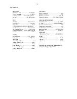
Specification ................................................................. 1-2
Measurement Setup ....................................................... 1-3
Service Aids ................................................................... 1-4
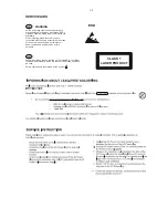
Instruction On CD Playability .................................1-5 to 1-6
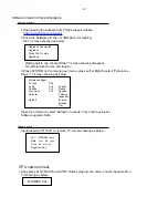
Software Version Check & Upgrade .............................. 2-1
Malfuction Check Chart .................................................. 2-2
Decoder Board ...................................................................11
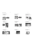
Disassembly Diagram
...................................................3-1
Block Diagram ................................................................. 4-1
Wiring Diagram................................................................. 4-2
VFD Display Board .............................................................5
Circuit diagram ........................................................... 5-1
Layout diagram ........................................................... 5-2
Prepositive Board ................................................................6
Circuit diagram ........................................................... 6-1
Layout diagram ........................................................... 6-2
AMP Board ..........................................................................7
Headphone,Button&AUX Board Diagram ..........................8
Circuit diagram ........................................................... 7-1
Layout diagram ........................................................... 7-2
TUNER Board ...................................................................10
Circuit diagram ......................................................... 10-1
Layout diagram ......................................................... 10-2
Circuit diagram ..............................................11-1 to 11-8
Layout diagram ............................................11-9 to 11-10
LAMP Board ....................................................................... 9
Explode View ................................................................12-1
Service Partlist ................................................... 13-1 to 13-3
Version 1.1
Содержание MCD 906
Страница 9: ... 0DOIXQFWLRQ IROORZ FKHFN FKDUW ...
Страница 14: ...5 2 5 2 VFD Display Board Layout Diagram ...
Страница 16: ...Prepositive Board Layout Diagram 6 2 6 2 ...
Страница 18: ...7 2 7 2 AMP Board Layout Diagram ...
Страница 22: ...Tuner Board Layout Diagram 10 2 10 2 ...
Страница 31: ...11 9 11 9 Decoder Board Layout Diagram TOP ...
Страница 32: ...11 10 11 10 Decoder Board Layout Diagram Bottom ...
Страница 33: ...D048 12 1 12 1 Explode View for 12 37 for 12 37 for 98 for 12 ...


