


Circuit Descriptions, Abbreviation List, and IC Data Sheets
9.
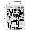
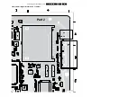
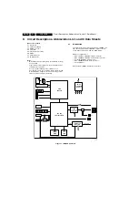
Figure 9-12 Block diagram audio processing
9.5.2
Audio Amplifier
The audio amplifier is an integrated class-D amplifier
(TDA8932T, item 7A01). It combines a good performance with
a high efficiency, resulting in a big reduction in heat generation.
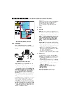
Principle
Figure 9-13 Principle Class-D Amplifier
The Class D amplifier works by varying the duty cycle of a
Pulse Width Modulated (PWM) signal.
By comparing the input voltage to a triangle wave, the amplifier
increases duty cycle to increase output voltage, and decreases
duty cycle to decrease output voltage.
The output transistors of a Class D amplifier switch from 'full off'
to 'full on' (saturated) and then back again, spending very little
time in the linear region in between. Therefore, very little power
is lost to heat. If the transistors have a low 'on' resistance
(RDS(ON)), little voltage is dropped across them, further
reducing losses.
A Low Pass Filter at the output passes only the average of the
output wave, which is an amplified version of the input signal.
In order to keep the distortion low, negative feedback is
applied.
The
advantage
of Class D is increased efficiency (= less heat
dissipation). Class D amplifiers can drive the same output
power as a Class AB amplifier using less supply current.
The
disadvantag
e is the large output filter. The main reason
for this filter is that the switching waveform results in maximum
current flow. This causes more loss in the load, which causes
lower efficiency. An LC filter with a cut-off frequency less than
the Class D switching frequency, allows the switching current
to flow through the filter instead of the load, thus reducing the
overall loss and increasing the efficiency.
DC-protection
A DC-detection circuit is foreseen to protect the speakers. It is
built around three transistors (items 7A05 to 7A07) and
generates a protection signal (DC_PROT) to the
microprocessor in case of a DC failure in the Class D
amplifiers.
9.6
HDMI
9.6.1
Introduction
Note:
Text below is an excerpt from the ”HDMI Specification”
that is issued by the HDMI founders (see
The High-Definition Multimedia Interface is developed for
transmitting digital signals from audiovisual sources to
television sets, projectors and other video displays.
HDMI can carry high quality multi-channel audio data and can
carry all standard and high-definition consumer electronics
video formats. Content protection technology is available.
HDMI can also carry control and status information in both
directions.
HDMI is backward compatible with DVI (1.0). Compared with
DVI, HDMI offers extra:
•
YUV 4:4:4 (3
×
8-bit) or 4:2:2 (up to 2
×
12-bit), where DVI
offers only RGB 4:4:4 (3
×
8 bit).
•
Digital audio in CD quality (16-bit, 32/44.1/48 kHz), higher
quality available (8 channels, 192 kHz).
•
Remote control via CEC bus (Consumer Electronics
Control): allows user to control all HDMI devices with the
TV's remote control and menus.
•
Smaller connector (SCART successor).
•
Less cables: e.g. from 10 audio/9 video cables to 3 HDMI
cables.
9.6.2
Implementation
The HDMI implementation is built around the IP4776CZ38
HDMI Interface for host-interface protection, which features:
•
Integrated high-level ESD protection, level shifting and
backdrive protection
•
All TMDS lines with integrated rail-to-rail clamping diodes
with downstream ESD protection of
±
8 kV according to IEC
61000-4-2, level 4 standard
•
Bidirectional level shifting N-channel FETs provided for
DDC clock and data channels
•
TMDS lines with
≤
0.05 pF matching of capacitance
between the TMDS pairs
•
Ultra low line capacitance of 0.7 pF per channel
•
HDMI 1.3 compliant
•
Backdrive protection.
Refer to figure “HDMI implementation” for details.
L
R
Y
Pb
Pr
HDMI 1
HDMI 2
Ext 1 - Scart 1
SMIC
TDA8890
LOC TOP
TDA15471/15421
Tuner
=
CV
B
S
L
R
SA
W
HDMI
MUX
HP
Standby uP
WT61P8S
CLASS D
TDA8932BT
Ext 2 - Scart 2
SIFIN1,SIFIN
267,68
1104
1103
IN4L,IN4R
52,51
OUTS1L, OUTS1R
62,61
IN2L, IN2R
48,45
OUTS2L ,OUTS2R
41,40
IN3L, IN3R
64,63
IN7L
IN7R
35,34
DS
P
INL
, D
S
P
IN
R
4,
5
MA
IN
O
U
T
L
, MA
IN
O
U
T
R
9,
10
SSIF
O
U
T
7
SIF1,2
SC1_AUDIO_IN
L,R
SC2_AUDIO_INL,R
SC1_AUDIO_OUT
L,R
SC2_AUDIO_OUT
L ,R
SIDE_AUDIO_IN L,R
CO
M
P
_A
UD
IO
_
IN
L
,R
TU
N
_S
IF
M
A
IN
_L
,R
TU
N
_
L,
R
AO
UT
0L
AO
UT
0R
55
,5
6
AI
N0
L
,AI
N
0
R
37,
38
SI
F
A
IN
53
AOUT1L
AOUT1R
61,62
AUDIO_LS_L,R
7A52
7A61,62
7A56,57
SC
2
_A
U
D
IO
_
M
U
T
E
L
,R
S
C
1
_A
U
D
IO
_M
U
TE
L,
R
ANTI_PLOP
AN
T
I_
P
L
O
P
LOUT,ROUT_SP
LO
U
T
,R
O
U
T
_
H
P
7A53
7A60
POWER_DOWN
MU
T
E
n
ST
A
N
D
B
Y
n
ENGAGE
7A06
7A07
7A05
DC_PROT
VD5
71
HP_DETECT
VC
L
K
68
SW
O
79
SAW-SW
I_1
8
170_04
8
.ep
s
3
1070
8
G_16860_080.eps
020207
+V
-V


