


3. The flat pack-IC on the CBA is affixed with glue, so
be careful not to break or damage the foil of each
pin or the solder lands under the IC when
removing it.
With Soldering Iron:
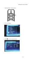
1. Using desoldering braid, remove the solder from
all pins of the flat pack-IC. When you use solder
flux which is applied to all pins of the flat pack-IC,
you can remove it easily. (Fig. S-1-3)
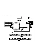
2. Lift each lead of the flat pack-IC upward one by
one, using a sharp pin or wire to which solder will
not adhere (iron wire). When heating the pins, use
a fine tip soldering iron or a hot air desoldering
machine. (Fig. S-1-4)
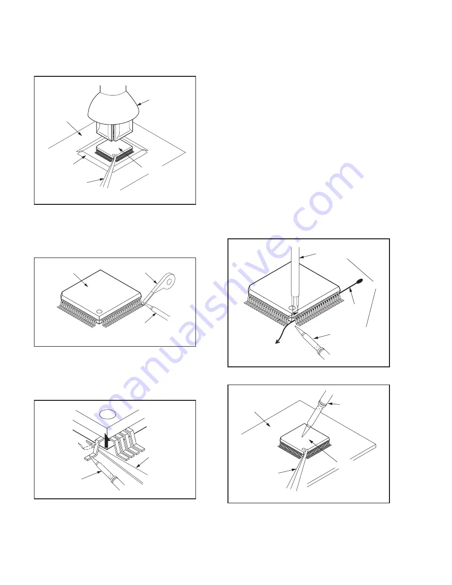
3. Bottom of the flat pack-IC is fixed with glue to the
CBA; when removing entire flat pack-IC, first apply
soldering iron to center of the flat pack-IC and heat
up. Then remove (glue will be melted). (Fig. S-1-6)
4. Release the flat pack-IC from the CBA using
tweezers. (Fig. S-1-6)
With Iron Wire:
1. Using desoldering braid, remove the solder from
all pins of the flat pack-IC. When you use solder
flux which is applied to all pins of the flat pack-IC,
you can remove it easily. (Fig. S-1-3)
2. Affix the wire to a workbench or solid mounting
point, as shown in Fig. S-1-5.
3. While heating the pins using a fine tip soldering
iron or hot air blower, pull up the wire as the solder
melts so as to lift the IC leads from the CBA
contact pads as shown in Fig. S-1-5.
4. Bottom of the flat pack-IC is fixed with glue to the
CBA; when removing entire flat pack-IC, first apply
soldering iron to center of the flat pack-IC and heat
up. Then remove (glue will be melted). (Fig. S-1-6)
5. Release the flat pack-IC from the CBA using
tweezers. (Fig. S-1-6)
Note: When using a soldering iron, care must be
taken to ensure that the flat pack-IC is not
being held by glue. When the flat pack-IC is
removed from the CBA, handle it gently
because it may be damaged if force is applied.
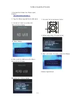
Hot-air
Flat Pack-IC
Desoldering
Machine
CBA
Flat Pack-IC
Tweezers
Masking
Tape
Fig. S-1-2
Flat Pack-IC
Desoldering Braid
Soldering Iron
Fig. S-1-3
Fine Tip
Soldering Iron
Sharp
Pin
Fig. S-1-4
To Solid
Mounting Point
Soldering Iron
Iron Wire
or
Hot Air Blower
Fig. S-1-5
Fine Tip
Soldering Iron
CBA
Flat Pack-IC
Tweezers
Fig. S-1-6
7-2
Содержание HTS3220
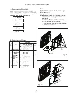
Страница 21: ...9 2 Fig D3 Fig D4 Fig D5 Cabinet Disassembly Instructions A10 A09 A09 A02 A02 A03 A03 ...
Страница 30: ...Main Unit VFD Display Board Layout Diagram 15 3 15 3 ...
Страница 35: ...Main Unit AMP Board Layout Diagram 17 4 17 4 ...
Страница 44: ...Main Unit Decoder Board Layout Diagram 18 9 18 9 ...
Страница 45: ...Subwoofer AMP Power Board Circuit Diagram 19 1 19 1 ...
Страница 46: ...Subwoofer AMP Power Board Circuit Diagram 19 2 19 2 IC5 TDA8920CJ ...
Страница 48: ...Subwoofer AMP Power Board Layout Diagram 19 4 19 4 ...
Страница 49: ...Main Unit Exploded View 20 1 20 1 ...
Страница 50: ...Subwoofer Exploded View 20 2 20 2 SUB016 For 98version ...
Страница 52: ...Revision List Revision List Version 1 0 Initial Release 21 1 ...