


7-1
•
Special information for BGA-ICs:
- always use the 12nc-recognizable soldering
temperature profile of the specific BGA (for de-
soldering always use the lead-free temperature
profile, in case of doubt)
- lead free BGA-ICs will be delivered in so-called
'dry-packaging' (sealed pack including a silica gel
pack) to protect the IC against moisture. After
opening, dependent of MSL-level seen on indicator-
label in the bag, the BGA-IC possibly still has to be
baked dry. (MSL=Moisture Sensitivity Level). This
will be communicated via AYS-website.
Do not re-use BGAs at all.
• For sets produced before 1.1.2005 (except products
of 2004), containing leaded solder-alloy and
components, all needed spare-parts will be available
till the end of the service-period. For repair of such
sets nothing changes.
• On our website
www.atyourservice.ce.Philips.com
you find more
information to:
• BGA-de-/soldering (+ baking instructions)
• Heating-profiles of BGAs and other ICs used in
Philips-sets
You will find this and more technical information within
the “magazine”, chapter “workshop news”.
For additional questions please contact your local
repair-helpdesk.
How to Remove / Install Flat Pack-IC
Special Information of BGA IC & Flat Pack-IC
1. Removal
With Hot-Air Flat Pack-IC Desoldering Machine:
1. Prepare the hot-air flat pack-IC desoldering
machine, then apply hot air to the Flat Pack-IC
(about 5 to 6 seconds). (Fig. S-1-1)
2. Remove the flat pack-IC with tweezers while
applying the hot air.
3. Bottom of the flat pack-IC is fixed with glue to the
CBA; when removing entire flat pack-IC, first apply
soldering iron to center of the flat pack-IC and heat
up. Then remove (glue will be melted). (Fig. S-1-6)
4. Release the flat pack-IC from the CBA using
tweezers. (Fig. S-1-6)
CAUTION:
1. The Flat Pack-IC shape may differ by models. Use
an appropriate hot-air flat pack-IC desoldering
machine, whose shape matches that of the Flat
Pack-IC.
2. Do not supply hot air to the chip parts around the
flat pack-IC for over 6 seconds because damage
to the chip parts may occur. Put masking tape
around the flat pack-IC to protect other parts from
damage. (Fig. S-1-2)
Fig. S-1-1
Содержание HTS3220
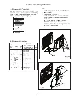
Страница 21: ...9 2 Fig D3 Fig D4 Fig D5 Cabinet Disassembly Instructions A10 A09 A09 A02 A02 A03 A03 ...
Страница 30: ...Main Unit VFD Display Board Layout Diagram 15 3 15 3 ...
Страница 35: ...Main Unit AMP Board Layout Diagram 17 4 17 4 ...
Страница 44: ...Main Unit Decoder Board Layout Diagram 18 9 18 9 ...
Страница 45: ...Subwoofer AMP Power Board Circuit Diagram 19 1 19 1 ...
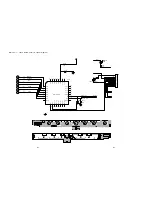
Страница 46: ...Subwoofer AMP Power Board Circuit Diagram 19 2 19 2 IC5 TDA8920CJ ...
Страница 48: ...Subwoofer AMP Power Board Layout Diagram 19 4 19 4 ...
Страница 49: ...Main Unit Exploded View 20 1 20 1 ...
Страница 50: ...Subwoofer Exploded View 20 2 20 2 SUB016 For 98version ...
Страница 52: ...Revision List Revision List Version 1 0 Initial Release 21 1 ...