background image

Service Modes, Error Codes, and Fault Finding

EN 21

LC8.2A LA

5.

For instructions on how to upgrade the MT8280 software, refer 
to ComPair.

5.6.3

Digital Module SW Upgrade

Detailed information will be published when these sets are 
actually on the market (not during this release of the Service 
Manual).

The software of the Digital Module can be flashed via USB.

5.7

Fault Finding and Repair Tips 

Notes: 

It is assumed that the components are mounted correctly 
with correct values and no bad solder joints. 

Before any fault finding actions, check if the correct options 
are set.

5.7.1

NVM Editor

In some cases, it can be convenient if one directly can change 
the NVM contents. This can be done with the “NVM Editor” in 
SAM mode. With this option, single bytes can be changed.

Caution: 

Do not change the NVM settings without 
understanding the function of each setting, because 
incorrect NVM settings may seriously hamper the 
correct functioning of the TV set!


Always write down the existing NVM settings, before 
changing the settings. This will enable you to return to the 
original settings, if the new settings turn out to be incorrect.

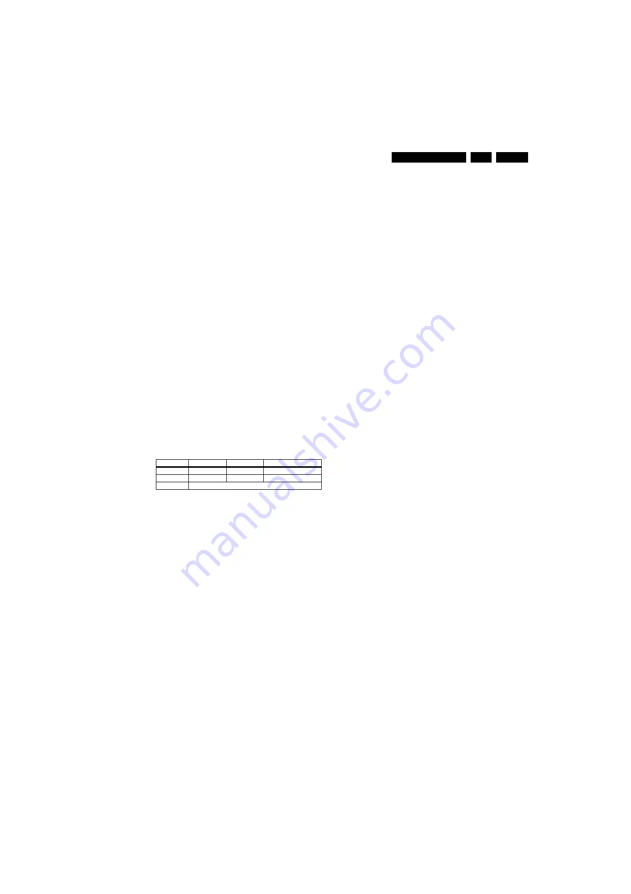
Table 5-3 NVM editor overview

5.7.2

Load Default NVM Values

It is possible to download default values automatically into the 
NVM in case a blank NVM is placed or when the NVM first 20 
address contents are “FF”. After the default values are 
downloaded, it is possible to start-up and to start aligning the 
TV set. To initiate a forced default download the following 
action has to be performed:
1.

Switch “off” the TV set with the mains cord disconnected 
from the wall outlet (it does not matter if this is from 
“Stand-by” or “Off” situation).

2.

Short-circuit the SDM jumpers on the SSB (keep short 
circuited).

3.

Press “P+” or “CH+” on the local keyboard (and keep it 
pressed).

4.

Reconnect the mains supply to the wall outlet.

5.

Release the “P+” or “CH+” when the set is “on” or blue LED 
is blinking.

When the downloading has completed successfully, the set 
should be into Stand-by, i.e. red LED on.
 

Alternative method (1):

1.

Go to SAM.

2.

Select NVM Editor.

3.

Select ADR (address) to 1 (dec).

4.

Change the VAL (value) to 170 (dec).

5.

Store the value.

6.

Do a hard reset to make sure new default values took 
place. 

Alternative method (2):

It is also possible to upload the default values to the NVM with 
ComPair in case the SW is changed, the NVM is replaced with 
a new (empty) one, or when the NVM content is corrupted.
After replacing an EEPROM (or with a defective/no EEPROM), 
default settings should be used to enable the set to start-up and 
allow the Service Default Mode and Service Alignment Mode to 
be accessed.

5.7.3

Start-up/Shut-down Flowcharts

On the next pages you will find start-up and shut-down 
flowcharts, followed by a trouble shooting flowchart, which 
might be helpful during fault finding.

Please note

 that some events are only related to PDP sets, 

and therefore not applicable to this LCD chassis.

Hex

Dec

Description

.ADR

0x000A

10

Existing value

.VAL

0x0000

0

New value

.Store

Store?

Содержание 47PFL5403

Страница 1: ...00Hz 28 Wiring Diagram 52 not available yet 29 Block Diagram Video 30 Block Diagram Audio 31 Block Diagram Control Clock Signals 32 SSB Test Point Overview 33 38 I2C IC Overview 39 Supply Lines Overview 40 7 Circuit Diagrams and PWB Layouts Diagram PWB Main Power Supply 42 Part 1 A1 41 43 44 Main Power Supply 42 Part 2 A2 42 43 44 DFI Panel DC DC AB01 45 55 56 DFI Panel Video Flow AB02 46 55 56 DF...

Страница 2: ...nnels 99 presets Tuner bands VHF UHF S H TV Colour systems PAL B G D K I SECAM B G D K Video playback NTSC PAL SECAM Supported computer formats 640 480 60 72 75 85 Hz 800 600 60 72 75 85 Hz 720 400 70 Hz 1280 768 60 Hz 1280 1024 60 Hz 1360 768 60 Hz Supported video formats 1080i 50 60 Hz 1080p 24 25 30 50 60 Hz 480i 60 Hz 480p 60 Hz 576i 50 Hz 576p 50 Hz 720p 50 60 Hz 1 1 2 Sound Sound systems ste...

Страница 3: ... rt Cinch Video CVBS In Audio In Ye Video CVBS 1 VPP 75 ohm jq Wh Audio L 0 5 VRMS 10 kohm jq Rd Audio R 0 5 VRMS 10 kohm jq S Video Hosiden Video Y C In 1 Ground Y Gnd H 2 Ground C Gnd H 3 Video Y 1 VPP 75 ohm j 4 Video C 0 3 VPPP 75 ohm j 1 2 2 Rear Connections Service Connector ComPair 1 SDA S I2C Data 0 5 V jk 2 SCL S I2 C Clock 0 5 V j 3 Ground Gnd H Aerial In IEC type EU Coax 75 ohm D HDMI1 ...

Страница 4: ...0 5 VRMS 10 kohm jq CVI Cinch Video YPbPr In Audio In Gn Video Y 1 VPP 75 ohm jq Bu Video Pb 0 7 VPP 75 ohm jq Rd Video Pr 0 7 VPP 75 ohm jq Wh Audio L 0 5 VRMS 10 kohm jq Rd Audio R 0 5 VRMS 10 kohm jq AV Out Cinch Video CVBS Out Audio Out Ye Video CVBS 1 VPP 75 ohm kq Wh Audio L 0 5 VRMS 10 kohm kq Rd Audio R 0 5 VRMS 10 kohm kq AV In Cinch Video CVBS In Audio In Ye Video CVBS 1 VPP 75 ohm jq Wh...

Страница 5: ...orms and voltages with D and without E aerial signal Measure the voltages in the power supply section both in normal operation G and in stand by F These values are indicated by means of the appropriate symbols Manufactured under license from Dolby Laboratories Dolby Pro Logic and the double D symbol are trademarks of Dolby Laboratories 2 3 2 Schematic Notes All resistor values are in ohms and the ...

Страница 6: ... serial number Digits 1 and 2 refer to the production centre e g AG is Bruges digit 3 refers to the B O M code digit 4 refers to the Service version change code digits 5 and 6 refer to the production year and digits 7 and 8 refer to production week in example below it is 2006 week 17 The 6 last digits contain the serial number Figure 2 1 Serial number example 2 3 6 Board Level Repair BLR or Compon...

Страница 7: ...ervice Positions 4 3 Assy Panel Removal ME8 Styling 4 4 Set Re assembly Notes Figures below can deviate slightly from the actual situation due to the different set executions Follow the disassemble instructions in described order 4 1 Cable Dressing Figure 4 1 Cable dressing 50 Hz basic sets I_17760_039 eps 030308 ...

Страница 8: ...Mechanical Instructions EN 8 LC8 2A LA 4 Figure 4 2 Cable dressing 50 Hz with AmbiLight Figure 4 3 Cable dressing 100 Hz sets with DFI panel I_17760_040 eps 040308 I_17760_041 eps 030308 ...

Страница 9: ... 2 2 Service Stands The MkII aluminium Service Stands are not suitable for this chassis Use the stands that come with the set instead 4 3 Assy Panel Removal ME8 Styling 4 3 1 Back Cover Warning Disconnect the mains power cord before you remove the back cover Note it is not necessary to remove the stand while removing the back cover Warning AmbiLight sets have an additional hatch located in the bac...

Страница 10: ... the unit sidewards from the back cover When defective replace the whole unit Figure 4 7 Ambilight Unit 4 3 3 Woofers Refer to next figure for details 1 Remove the screws 1 and 2 and lift the whole unit from the back cover Take the speakers out together with their casing When defective replace the whole unit I_17760_042 eps 040308 2 2 2 2 2 2 2 2 2 2 2 2 2 2 2 2 2 2 2 1 1 H_17740_022 eps 230108 3 ...

Страница 11: ...it out of the set When defective replace the whole unit Figure 4 11 Key Board 4 3 7 Display Supply Panel Refer to next figure for details 1 Unplug connectors 1 2 Remove the fixation screws 2 3 Take the board out Figure 4 12 Display Supply Panel 4 3 8 Small Signal Board SSB Refer to next figure for details Caution it is mandatory to remount all different screws at their original position during re ...

Страница 12: ...an now be taken out of the set Figure 4 14 DFI Panel 4 3 10 LCD Panel Refer to next figures for details 1 Remove the stand 2 Unplug the LVDS connector s 1 and remove the adhesive tape 1a Caution be careful as this is a very fragile connector 3 Unplug the connectors 2 4 Remove the fixation screws 3 from rim 5 Take the rim from the set 6 Remove the fixation screws 4 and 5 7 Lift the subframe from th...

Страница 13: ...Mechanical Instructions EN 13 LC8 2A LA 4 Figure 4 15 LCD Panel I_17760_045 eps 060308 1 1a 4 4 4 4 4 4 4 4 2 2 2 5 5 5 5 5 5 5 5 3 3 ...

Страница 14: ...er Notes While re assembling make sure that all cables are placed and connected in their original position See figure Cable dressing Pay special attention not to damage the EMC foams Ensure that EMC foams are mounted correctly one is located above the LVDS connector on the display between the LCD display and the metal sub frame ...

Страница 15: ...e TV set via I2C with help of ComPair To do this ComPair has to be connected to the TV set via the ComPair connector which will be accessible through the rear of the set without removing the rear cover 5 2 1 General Some items are applicable to all Service Modes or are general These are listed below Life Timer During the life time cycle of the TV set a timer is kept It counts the normal operation ...

Страница 16: ...st know exactly what he is doing as it could damage the television set Figure 5 2 Service jumper SSB component side On Screen Menu After activating SDM the following screen is visible with SDM in the upper right corner of the screen to indicate that the television is in Service Default Mode Figure 5 3 SDM menu Menu explanation HHHHH Are the operating hours in decimal AAAABCD X YY See paragraph Ser...

Страница 17: ...buffer is cleared 7 Options Used to set the option bits See Options in the Alignments chapter for a detailed description 8 Tuner Used to align the tuner See Tuner in the Alignments chapter for a detailed description 9 RGB Align Used to align the White Tone See White Tone in the Alignments chapter for a detailed description 10 NVM Editor Can be used to change the NVM data in the television set See ...

Страница 18: ...ormation about the audio system of the selected transmitter MONO STEREO NICAM 13 HDAU HDMI audio stream detection YES means audio stream detected NO means no audio stream present Only displayed when HDMI source is selected 14 FORMAT Gives information about the video format of the selected transmitter 480i 480p 720p 1080i 15 DFR SW ID Referring to bolt on SW ID 16 FPGA FW Only applicable to sets wi...

Страница 19: ...ailure The last errors stored in the NVM are shown in the Service menu s This is called the error buffer The error code buffer contains all errors detected since the last time the buffer was erased The buffer is written from left to right When an error occurs that is not yet in the error code buffer it is displayed at the left side and all other errors shift one position to the right An error will...

Страница 20: ... short blinks 5 5 2 Displaying the Entire Error Buffer Additionally the entire error buffer is displayed when Service Mode SDM is entered In case the TV set is in protection or Stand by The blinking LED procedure sequence as in SDM mode in normal operation must be triggered by the following RC sequence MUTE 062500 OK In order to avoid confusion with RC5 signal reception blinking this blinking proc...

Страница 21: ...sible to start up and to start aligning the TV set To initiate a forced default download the following action has to be performed 1 Switch off the TV set with the mains cord disconnected from the wall outlet it does not matter if this is from Stand by or Off situation 2 Short circuit the SDM jumpers on the SSB keep short circuited 3 Press P or CH on the local keyboard and keep it pressed 4 Reconne...

Страница 22: ...or 300ms Blank Picture Picture Mode Setup Detection Error 5 Trident Protection Yes DVB recording mode No Yes WP for NVM STANDBY LOW Standby Normal Mode Recording Mode finished Software Shutdown LED WHITE for Normal mode LED RED for Recording mode User wake up the sets in DVB recording mode BLOCK RC Key Enable RC Key Error 7 Error 8 Error 9 Error 11 Error 3 Protection Standby Normal Mode RED LED Di...

Страница 23: ...DP CTRL_DISP1 HIGH FHP PDP CTRL_DISP4 LOW Off Air Downloading Recording Mode IBOZ send shut down command BL_ADJ PWM duty cycle 100 Enable Audio Mute Port Assignment in STANDBY 300ms 20ms Total 360ms 40ms Wait for 3000ms Sets go to standby here Blocking for the next start up to ensure power supply discard properly Disable Power Down INT DC_PROT_INT Wait for 3000ms Except power tact switch BL_ADJ LO...

Страница 24: ...GH Wait 5000 ms Re start Start up End No Notes 1 Power Down INT will based on fall edge triggering 2 3V3STBY will stay for 15ms software must perform WP for NVM within 15ms Poll the Power Down INT for 5 times End Avoid false trigger Start Mute Audio VIdeo No End Avoid false trigger is DC_PROT LOW for 3 sec Log Error Code STANDBY HIGH WP for NVM Error 1 Protection End Yes Yes I_17760_027 eps 150208...

Страница 25: ...Service Modes Error Codes and Fault Finding EN 25 LC8 2A LA 5 Figure 5 11 Troubleshooting flowchart Code I_17760_049 eps 030308 ...

Страница 26: ...Service Modes Error Codes and Fault Finding EN 26 LC8 2A LA 5 Personal Notes E_06532_012 eps 131004 ...

Страница 27: ...D 2 GND 1 LEFT 1P10 1 LIGHT SENSOR 2 GNDSND 3 RC 4 LED2 5 3V3 STANDBY 6 LED1 7 KEYBOARD 8 5V 9 KEYBOARD 1P11 1 GND 2 KEYBOARD 3 3V3STBY 4 TACT_SWITCH_INT CN1 1 N 2 L 1206 B04C 6 GND_24V 5 24V_BOLT ON 4 GND_24V 3 24V_BOLT ON 2 GND_24V 1 24V_BOLT ON AMBI LIGHT UNIT IN BACK COVER 1175 J1 1 GND 2 KEYBOARD 3 3V3STBY 4 INTERRUPT 8308 J4 8 I2C SEL2 7 3 3V 6 GND 5 S SDA 4 S SCL 3 GND 2 24V 1 24V J2 7 GND ...

Страница 28: ... 1 GND 2 KEYBOARD 3 3V3STBY 4 TACT_SWITCH_INT CN1 1 N 2 L 1206 B04C 6 GND_24V 5 24V_BOLT ON 4 GND_24V 3 24V_BOLT ON 2 GND_24V 1 24V_BOLT ON AMBI LIGHT UNIT IN BACK COVER 1175 J1 1 GND 2 KEYBOARD 3 3V3STBY 4 INTERRUPT 8308 J4 8 I2C SEL2 7 3 3V 6 GND 5 S SDA 4 S SCL 3 GND 2 24V 1 24V J2 7 GND 6 3 3V 5 I2C SEL2 4 I2C SEL1 3 S SDA 2 GND 1 S SCL J1 4 GND 3 24V 2 GND 1 24V J4 1 24V 2 24V 3 GND 4 S SCL 5...

Страница 29: ...Block Diagrams Test Point Overview and Waveforms 29 LC8 2A LA 6 Wiring Diagram 52 WIRING 52 Not available on time of publishing I_17760_067 eps 040308 ...

Страница 30: ...H U10 AIN_V VGA_V 1 6 10 11 5 15 VGA CONNECTOR DPA_HS DPA_VS DPB_DE DPA_CLK 1 5 4 1103 38MHz9 38MHz 1 5 4 1105 ONLY FOR CHINA 38MH DYNAMIC FRAME INSERTION AB05 FPGA POWER CONTROL 1F51 LVDS CONNECTOR TO DISPLAY 1F52 5 4 3 9 40 49 50 1 32 2 1 VDISP 1F50 10 11 12 13 14 15 17 18 20 21 22 23 25 26 27 28 39 30 32 33 35 36 37 38 40 7F18 EP2C35F484C7N CYCLONE II FPGA DFI 7CA0 EDD1216AJTA DDR SDRAM 1 2Mx16...

Страница 31: ...DEMODULATOR TUNER AGC VIF AGC TAGC SIF AGC I2C BUS TRANSCEIVER MAD SCL SDA SUPPLY 12 SIOMAD 5VS 1411 18M432 67 68 XTALIN XTALOUT 3A26 5A03 5A04 SC1_AUDIO _MUTE_R SC1_AUDIO _MUTE_L B06B 15 1104 4M0 SUPPLY SUP_D 8V SUP_A 12 13 61 62 39 7A05 7A07 3607 3611 57 58 SC5 IN L SC5 IN R VGA_AUDIO_IN_L VGA_AUDIO_IN_R CVI 1 AUDIO L R IN 3E21 3E23 20 HDMI_I2S_SCK 17 86 HDNI_I2S_WS 18 85 HDMI_I2S_SD 20 81 CL3 W...

Страница 32: ...T B05A 99 LCD_PWR_ON B04E 19 DDC_RST B07A 23 SAW_SW B02 78 MUTEn 75 BL_ON_OFF B01A 74 ANTI_PLOP B05B I_17760_064 eps 040308 7310 M29W800DT EPROM 1Mx8 512Kx16 A 0 19 AD 0 7 A 0 7 AD 0 7 J17 45 CS J20 42 RD J19 44 WR J18 38 ALE_EMU CPU_RST 12 10 26 48 CE 11 28 7312 BD45275G 4 3V3 VOUT 2 3 3V3_STBY 5 G17 BL_ADJUST_PWM CONTROL 7C02 7C04 B01A 22 BL_BOOST B01A 7M07 SII9185ACTU HDMI_MUX_TX 19 1 18 2 RXx_...

Страница 33: ...2 IFB4 B3 IFB5 B3 IFB6 B3 IFB7 B3 IFB8 B3 IG64 A5 IG64 A5 IG69 A5 IGB1 B5 IGB1 B5 IGB2 B5 IGB2 B5 IGE8 A5 IGE8 A5 IGF4 A5 IGF7 A5 IGF7 A5 IGF8 A5 IGF9 A5 IGH2 A5 IGH3 A5 IGH4 A5 IGH5 A5 IGH6 A5 IGH6 A5 IGH9 A5 IH06 E3 IH06 E3 IH09 E2 IH09 E2 IHD0 E2 IHDA F2 IHF4 E2 IHF4 E2 IHF8 E2 IHF8 E2 IHF9 E1 IHR0 E3 IHR3 E3 IHR3 E3 IHR4 E2 IHR4 E2 IHR5 E2 IHR5 E2 IHR6 E2 IHR9 E2 IHR9 E2 IHRA E2 IHRB E2 IHRC E...

Страница 34: ...34 LC8 2A LA 6 Block Diagrams Test Point Overview and Waveforms SSB Test Points Part 1 Top Side Part 1 H_16770_059a eps 270307 ...

Страница 35: ...Block Diagrams Test Point Overview and Waveforms 35 LC8 2A LA 6 SSB Test Points Part 2 Top Side Part 2 H_16770_059b eps 260307 ...

Страница 36: ... I381 F5 I382 F5 I383 F4 I384 E4 I385 E5 I386 E4 I387 D2 I388 D3 I389 E3 I390 E3 I391 D3 I392 D3 I393 D3 I394 D5 I395 D4 I396 C4 I397 D4 I398 D4 I399 D4 I400 D4 I401 D4 I402 E4 I403 D4 I404 E3 I405 E4 I406 D4 I407 E4 I408 E4 I409 D4 I410 E4 I411 D4 I412 D3 I413 E4 I414 E4 I415 E3 I416 E3 I417 E3 I418 E3 I419 E3 I420 E3 I421 E3 I422 E3 I423 D4 I424 E4 I425 D3 I426 E3 I427 E3 I428 E4 I429 E4 I430 E4...

Страница 37: ...Block Diagrams Test Point Overview and Waveforms 37 LC8 2A LA 6 SSB Test Points Part 1 Bottom Side H_16770_060a eps 270307 Part 1 ...

Страница 38: ...38 LC8 2A LA 6 Block Diagrams Test Point Overview and Waveforms SSB Test Points Part 2 Bottom Side H_16770_060b eps 270307 Part 2 ...

Страница 39: ...BY 3353 7302 PCA9515ADP 3 2 6 7 7303 PCA9515ADP 3 2 6 7 3V3_SW 3359 3360 3V3_SW 3362 3361 IIC_SDA_SIDE IIC_SCL_SIDE XCIN XCOUT 3V3_STBY 3L98 3L97 8 9 H17 H18 7C01 WX69 7569 VIDEO PROCESSOR 3C08 3C09 ERR 05 PE H1 7700 EP2C5F256C7N CYCLONE II FPGA AMBI LIGHT ERR 17 3202 3201 MAIN_SDA MAIN_SCL ITV_I2C_SDA ITV_I2C_SDA 3R26 3R25 1R01 1 2 LVDS CONNECTOR TO DISPLAY OR TO DFI PANEL 3 2 7411 MSP4450L AUDIO...

Страница 40: ...TBY 3V3_STBY B01a 5V_SW 5V_SW B01b 2V5_VDDMQ 2V5_VDDMQ B04b DDR_VREF DDR_VREF B04b FPGA_BL_DIMMING FPGA_BL_DIMMING RES DDR_VREF 3D15 1 1206 1205 1 24V 5704 FPGA_BL_DIMMING FPGA_BL_DIMMING RES 12V_DISP 12V_DISP VDISP 5R02 3V3_SW 3V3_SW 7R05 3402 5401 5402 12V_AUDIO 12V_AUDIO VDD VDDA B01a 3A01 5A07 5A05 12V_AUDIO 12V_AUDIO VSS VSSA 3A02 5A08 5A06 5V_SW 5V_SW 3V3_STBY 3V3_STBY B01b B01a DC_5V 1E01 9...

Страница 41: ...V 1N4007 D910 C921 0 047u 450V R901 1 FUSIBL E C902 33u 450V R904 1K 1W BD2 S1NB8 0 R7 R950 5 1 1206 T901 EF 12 6 C950 1KP 1206 C920 ZD908 P6KE300A 5 1K R905 R906 10K Q900 4403 C912 47u 63V EGP10D D903 FQPF3N80C Q905 C914 0 1u ZD902 20A ZD602 3 3B C956 2 2u R903 2 1W ZD951 1N5917B D950 SB340 R916 5 1 1206 BYV26E D909 1 2 PC901 PC123 D906 BAV103 FB902 3 5x6 C916 47P 1KV 1 2 R952 2k R954 2k C954 0 4...

Страница 42: ... UU35 T301 C317 0 01u 1206 R320 40 2 C315 0 47u 450V R218 200 D307 BAV99 CN3 D317 BAS316 D212 BAS316 D305 BAV99 CN2 D304 BAS316 D306 BAS316 R327 27 2W R321 27 2W R341 1K C319 0 01u R344 60 4K R342 D312 R340 1K C958 1u R216 100 R963 100K 4403 Q604 D713 BAS316 D710 BAS316 C717 0 1u 1 4 IC703 LM324 C219 0 1u CN7 R736 3 01K R755 100K R735 2K D703 BAS316 1Kp C716 R728 10K 2N7002 Q304 IC703 LM324 1 4 R7...

Страница 43: ...Circuit Diagrams and PWB Layouts 43 LC8 2A LA 7 Layout Main Power Supply 42 Top Side H_16750_070 eps 110108 ...

Страница 44: ...44 LC8 2A LA 7 Circuit Diagrams and PWB Layouts Layout Main Power Supply 42 Bottom Side H_16750_071 eps 110108 ...

Страница 45: ...U68 H2 IU69 E1 IU70 D2 IU37 IU20 1 470R 3U70 39K 3U32 6K8 3U75 100n 2U00 IU06 470R 3U74 1 2U20 100n 3U63 1K0 FU10 FU04 7U07 BC817 25W IU35 3U27 6K8 1 3U25 220R IU52 2U31 1u0 1K0 3U24 7U13 2 BC847BPN 5 3 4 3U04 100R IU50 47u 2U09 IU47 IU43 FU06 9U03 FU05 10K 3U35 1u0 2U40 5U00 10u 2U21 47u 5 6 4 3 7U01 2 SI4936ADY BZG05C3V3 6U02 IU07 IU34 GND SIG BC847BW 7U05 3n3 2U08 IU21 GND SIG 3U72 100R 2U24 3n...

Страница 46: ... 5F63 DLW21S 1 2 4 3 1 2 4 3 2F09 RES 10p 5F06 DLW21S 2F04 RES 10p 10p RES 2F0V 1 2 4 3 DLW21S 5F62 10p 2F83 RES 5F05 1 2 4 3 DLW21S 3FHS 180R 10p RES 2F1A 5F64 1 2 4 3 3 DLW21S 5F08 DLW21S 1 2 4 FF36 1 2 4 3 DLW21S 5F78 3F58 120R 120R 3F56 180R 3F54 120R 3F52 3F50 120R 3F64 180R RES DLW21S 1 2 4 3 10p 2F1N 5F70 FF0M FF0L FF0K FF0H FF0J FF0F FF0E FF0D FF0C FF0B 10p 2F4A RES FF0Q 100R 3F89 3F7J 120...

Страница 47: ... 10 11 Video clock RESERVED CLOCK B C D E F G H 30R 3V3 5F22 100R 3FHV RES 1F43 1F33 1F42 IFC9 1F31 3V3 9F09 IFC3 1F41 IFC7 1F48 2 1 4 3 DSO751SV 27M0 7F85 2FD2 100n 30R 5F21 1F32 1F47 IFC0 100n 2FD3 RES 9F08 3FJA 1K0 3FJC 33R 100R 3FA9 2FD4 100n 1F35 1F44 5F20 6 4 3 7 8 30R Φ SCD 7F50 EPCS4SI8 5 1 2 3FH1 100R IF29 3V3 IFD1 1F30 100n 2FD1 IFC1 IF13 3V3 1 4 3 IF14 7F86 27M0 DSO751SV 2 1F34 IFC8 1F4...

Страница 48: ...SUPPLY 1 2 3 4 1 2F17 B3 2F18 B4 2F19 B3 2F21 B3 7F35 A3 7F36 B3 9F13 A2 IF10 A2 IF1U A3 2F17 RES RES 100n IF10 9F13 7F36 RES 1 3 2 IF1U LD1117DT25 1u0 2F18 RES 1 3 5 7F35 LD3985M25 4 2 RES RES 100n 2F21 12V RES 2F19 100n 2V5 STAB 3V3 AB04 AB04 H_16800_013 eps 180407 3139 123 6188 2 Personal Notes E_06532_012 eps 131004 ...

Страница 49: ...S4SI8 7F31 SCD Φ 5 1 2 RES RES 30R 5F26 RES 5F23 30R 5F53 30R 2FJP 4u7 10n 2FHS FF3L 3F76 10K 30R 5F57 2FJA 10n 100p 2FLL 2FLK 10n 100p 2FLJ 2FLH 100p 2FHF 10n 2FHE 10n IFB2 5F58 30R 3F86 RES 1K0 IFB1 SML 310 6F33 3F82 100R 10n IFA6 2FJL 3F14 10K FF3K 2FH4 10n BC847BS 7F34 2 5 3 4 2FJF 10n RES RES 30R 5F51 3F05 1K0 2FJ7 10n RES 30R 5F50 5F49 30R 10n 2FHH 10n 2FJC IFA9 IFA1 IFA5 6F32 SML 310 4 5 6 ...

Страница 50: ...O27 LVDS7n T6 T1 IO17 LVDS14n T2 IO18 LVDS13p P4 IO19 LVDS13n R4 IO1 LVDS25p M5 IO20 LVDS12p U1 IO21 LVDS12n U2 IO10 LVDS20n N4 IO11 VREFB1N0 P3 IO12 LVDS18p P5 IO13 LVDS18n P6 IO14 LVDS17p R1 IO15 LVDS17n R2 IO16 LVDS14p BANK1 7F18 3 EP2C35F484C7N CLK2 LVDSCLK1p M1 CLK3 LVDSCLK1n M2 T17 GNDD_PLL4 V5 GNDG_PLL1 E17 GNDG_PLL2 F5 GNDG_PLL3 V18 GNDG_PLL4 GNDA_PLL1 E16 GNDA_PLL2 F7 GNDA_PLL3 V16 GNDA_P...

Страница 51: ...0n 2F5W 3F5C 220R 5F28 RES 2F6C 10n 10n 2F5M 58 64 21 2F5Q 100p 49 34 48 66 6 12 52 1 18 33 3 9 15 55 61 25 43 50 53 42 23 47 51 13 54 56 20 16 14 17 19 62 63 65 5 7 8 10 11 45 46 24 2 4 57 59 60 37 38 39 40 26 27 22 44 29 30 28 41 31 32 35 36 SDRAM 2Mx16 Φ DDR EDD1216AATA 5B E 7CA2 22R 3F4M 3F4L 22R 3F4J 22R 22R 3F4G 100n 2F5N 3F4T 22R 22R 3F5N 3F5M 22R 100n 22R 3F5L 2F6F 3F5J 22R 3F5F 22R 3F5E 2...

Страница 52: ...R 10n 2V51 560R 3CD7 560R 3CD8 3CB1 22R 10n 2V39 220R 3CE1 22R 3CC7 16V 22u 2V34 3CD2 22R ICA0 VREF DDR2 3CB5 22R VREF DDR2 10n 2V55 FF92 3CC1 22R 2V43 10n 22R 3CA3 2V50 10n 22R 3CA8 22R 3CD3 2V54 10n 2V5 DDR2 2V45 100p 2V5 DDR2 2V42 10n 3CD9 560R 3CD6 560R 22R 3CC9 22R 3CB6 22R 3CB7 10n 2V53 2V52 10n VREF FPGA2 3CC3 22R 22R 3CC2 3CA2 22R 3CA4 22R 22R 3CB2 3CA9 22R 3CE2 220R 2V5 3CA6 22R 2V5 DDR2 ...

Страница 53: ...NC 2 SCL0 7 SCL1 3 SDA0 6 SDA1 8 VCC RES 5 EN 4 GND PCA9515ADP 7F10 FF1A 9F2F 47R 3F13 RES 3F48 3V3 330R 47R 3F2A 3F3B 3V3 4K7 120R 5F15 120R 5F17 5V 9F31 IF07 10K 3F21 12V SSB 100n 2F95 FF17 9F2H RES 120R 5F0J RES IF19 47R 3F31 10K 3F39 9F2I RES 9F28 6F07 SML 310 5F14 120R 9F29 1 3 2 BC847BW 7F08 10K 3F1Z 4K7 3F24 RES 9F30 2F35 10p 9F2S 100p 2F45 3V3 100p 2F2E IFD7 220R RES 5F0K RES 47R 3FJD 100p...

Страница 54: ...2 2F62 A3 2F63 A3 2F64 A3 2F65 A3 2F66 A3 B C D E F 2F20 A2 2F22 D2 2F23 D3 2F24 H13 2F25 B2 2F26 B3 2F27 B3 2F28 B3 2F29 B2 2F31 B2 2F44 E14 5 6 7 8 9 FOR FACTORY 14 A B C D E F G H I A 1F02 E12 1F03 I5 2F10 B3 2F11 B4 2F12 B4 2F13 B4 2F14 G9 2F15 I13 USE 2F16 B3 8 9 10 11 12 13 14 1 2 3 4 10 11 12 13 G H I 2V5M 1 2 3 4 5 6 7 3F6S 100R 10K 3F7B FF83 8 9 1F02 1 2 3 4 5 6 7 100R 3F47 3F6U 470R IF55...

Страница 55: ...F5V A2 3F5W A2 3F5Y A2 3F5Z A2 3F60 A2 3F61 A2 3F62 A2 3F63 A2 3F64 A2 3F65 A2 3F66 A2 3F67 A2 3F68 A2 3F69 A2 3F6A A2 3F6B A2 3F6C A2 3F6D B1 3F6K C1 3F6L C1 3F6M C1 3F6Q B1 3F6R B1 3F6S C1 3F6T C1 3F6U C1 3F6V C1 3F6W C1 3F6Z B1 3F70 A2 3F71 A2 3F78 C1 3F79 C1 3F7A B1 3F7B C1 3F7G C1 3F7H C1 3F7J A3 3F7K A3 3F7L A3 3F7M A3 3F7N A3 3F7P A3 3F7Q A3 3F7R A3 3F80 C1 3F82 C1 3F84 C1 3F85 C1 3F86 C1 3...

Страница 56: ...FLS A3 2FLT B3 2FLU B3 2FLV B3 2FLW B3 2FLY B3 2FLZ B3 2U00 C1 2U04 B1 2U05 B1 2U07 C1 2U08 C1 2U11 B1 2U15 B1 2U17 C1 2U18 B1 2U19 C1 2U20 B1 2U23 C1 2U24 C1 2U26 B1 2U27 B1 2U28 B1 2U29 B1 2U30 C1 2U31 C1 2U33 B1 2U34 C1 2U36 C1 2U37 C1 2U39 C1 2U40 C1 2V00 B2 2V01 A2 2V03 B1 2V04 B1 2V05 B1 2V33 A2 2V35 B1 2V39 B2 2V40 B2 2V41 B2 2V42 B2 2V43 A2 2V44 A2 2V45 B2 2V46 B2 2V50 A1 2V51 A2 2V52 B1 2...

Страница 57: ...5 F 3P48 A4 FP17 IP10 7P06 2 SI4936BDY 5 6 4 GNDDC1 2V5_SW FP23 12V_DISP 2P43 3n3 FP16 1 470R 3P76 IP12 12V_DISP 2P79 100n GNDDC1 2P59 GNDDC1 IP17 100u 16V 2P80 100n 1K0 3P38 5V_TCON 10R 3P61 GNDDC1 3P77 3K9 IP29 IP33 6P14 BAS316 2P87 1n0 IP39 2P89 100u 16V 2 4 FP11 TS431AILT 7P09 5 3 1 3P79 1K0 1K2 3P74 3V3_SW 100n 2P81 FP24 2P20 100p 3P78 470R 1 6K8 3P68 GNDDC1 IP43 FP30 10R 3P25 3V3_SW FP20 6K8...

Страница 58: ... B5 7Q11 D3 3Q38 D6 IQ28 D2 3 6 IQ26 D4 3Q20 B3 1 2Q78 A4 11 3 3Q77 G9 7 8 2 1 1V8_SW 1u0 2Q31 2Q78 1u0 BC817 25W 7Q05 2Q30 22u 100n GNDDC2 2Q07 2Q49 100p 3Q70 1K8 5Q02 10u 2Q41 100n 5V_SW 2Q43 3n3 IQ23 IQ24 2Q54 100n 1 2Q58 1u0 3Q59 470R 3Q41 3K3 2Q39 100n 5 6 4 3 7 8 2 1 SI4936BDY 7Q06 2 3Q77 SI4936BDY 7Q06 1 1K0 1 22n 2Q73 1 2 SI4936BDY 7Q07 1 5Q09 10u 2Q46 100u 16V 3Q48 3Q47 68R 68R 1K8 2Q29 2...

Страница 59: ...356 DEMODULATOR 5122 J14 6110 B8 Y K9352 UV1316E 2V1 2V3 1102 3 10 K6274k 2123 F4 4 E A B 11 G H Y C 2133 H7 1 3133 H13 3 2125 F3 5 2127 F5 7 2129 I14 10n 2131 I14 3V3_SW K7257M F118 C3 I136 J5 I151 J14 AP CHINA FOR EUROPE ONLY RES K9362 Y RES LATAM UV1316E I102 C14 7134 RES I133 J5 I141 D10 10n 12 9 I J 2141 J4 L 11 13 D 15 14 8 22K 3193 39K 3115 F117 3118 2K2 1SS356 6103 2122 15p F142 4K7 3191 1...

Страница 60: ...357 F356 F361 47K 3397 10M I318 4303 1301 3315 100R 3317 330R 100R 3386 3V3_STBY I308 I367 15K 3393 12V_DISP 3L72 47K 3V3_SW 3362 3K3 F362 I398 2344 33p F369 2342 10n 47R 3390 BAS316 6301 6312 BZX384 C6V8 1306 3349 10K 3387 100R 3V3_SW 3396 1K0 I360 F327 I312 F360 47R 3394 IL37 I362 3V3_STBY I356 I302 7L10 BC847BW 1 2 4 8 7 NL27WZ08USG 7323 1 12 37 27 46 11 4326 40 42 44 30 32 9 10 13 14 28 15 31 ...

Страница 61: ...LCX14T 33R 5C12 3V3_SW 3V3_SW 2C64 10u 6 3V 2C97 10u 6 3V 14 12 100n 2C96 74LCX14T 7C03 6 13 7 11 7 14 10 74LCX14T 7C03 5 3V3_SW 5V_SW 3C31 22R 3C36 22R 5 7 14 6 1 7 14 2 7C03 3 74LCX14T 7C03 1 74LCX14T 3C07 100R FC03 FC01 4K7 3C22 100R 2C27 3C09 10u 6 3V 4K7 3C29 3C32 4K7 2C03 100n 3C34 22R 74LCX14T 3 7 14 4 7C03 2 FPGA_BL_DIMMING 3C25 10K 4C08 100R 3C24 2C73 10u 18p 2C02 3V3_SW 4K7 3C44 2C29 10u...

Страница 62: ...NC2 17 NC3 25 NC4 43 NC5 53 NC6 42 DQ2 5 DQ3 7 DQ4 8 DQ5 10 DQ6 11 DQ7 13 DQ8 54 56 DQ9 DQ0 2 DQ1 4 DQ10 57 DQ11 59 DQ12 60 DQ13 62 DQ14 63 DQ15 65 BA1 27 CAS_ 22 CK 45 CKE 44 CK_ 46 24 CS_ 19 DNU1 50 DNU2 A3 32 A4 35 A5 36 A6 37 A7 38 A8 39 A9 40 BA0 26 A0 29 A1 30 28 A10 AP A11 41 A2 31 7D01 K4D261638K 6 3D09 15R 3D02 3 3 22R 2V5_VDDMQ 3D48 2 2 7 1K0 3D16 22R 2D34 100n 2 7 3D44 3 3 6 22R 3D44 2 ...

Страница 63: ...TWARE DEBUGGER 3232 B4 3231 B4 1205 E7 1206 E8 E D C B A 2216 F2 2215 F2 2214 B4 2211 B1 2210 F5 2209 F4 2208 F4 2207 F4 2206 F4 2205 F4 2204 E1 2203 E2 2202 D6 2201 D5 3203 D2 3202 D5 3204 D1 RES 3207 F5 2218 F2 3205 D1 3201 C5 2 CONNECTORS OVERLAPPING 7PIN 3206 D1 2219 F3 3225 E5 3224 E5 3222 E5 1203 C6 7 1202 E3 1204 B5 F FOR PWM AL DRIVER 7 6 5 4 3 2 1 6 5 4 3 2 1 8 F E D C B A 8 2207 1n0 2203...

Страница 64: ... 2719 2710 2717 4u7 5705 30R I730 2721 10n 2711 M7 P10 P7 T15 T2 10n A15 A2 C10 C7 E10 E7 B16 G14 K14 R16 M10 E12 L6 F11 G9 H10 H7 J7 B1 G3 K3 R1 E8 E9 G8 M6 E11 L5 N5 D12 F12 M5 P8 P9 R15 R2 T1 T16 B15 B2 C8 C9 H3 H8 H9 J14 J3 J8 J9 K9 M8 A16 M9 EP2C5F256C7N Φ POWER 7700 6 A1 H14 I729 D9 E13 E15 2V5out FPGA K8 N3 N4 N6 N7 P6 R6 C16 D1 D2 D7 F14 F5 G4 H6 J10 J6 K13 K6 K7 C15 Φ NC EP2C5F256C7N 7700...

Страница 65: ...R 4R03 FR44 5V_TCON 6R02 BZX384 C5V6 7R07 PDTC114ET FR63 FR46 FR57 25V 220u 2R11 4R32 4 FR59 47K 3R10 2R01 2R02 100p 100p 100R 3R25 4R11 33R 4R10 5R02 4R35 2 DLW21S 1R09 BZX384 C6V8 FR21 6R04 100p 2R24 3R53 100R 12V_DISP FR27 FR25 2R23 100p 100R 3R54 3R26 DLW21S 1R03 100R 4R07 4R05 4R06 FR37 FR61 FR55 FR40 3R49 IR08 4K7 4R02 4R12 1R08 DLW21S FR29 2R10 1u0 3R55 22R 4K7 3R50 FR23 4K7 3R51 VDISP FR34...

Страница 66: ...404 12u 330p 2421 2444 470p 470p 2442 2448 100R 3417 3402 1R0 I432 5V_SW 3p3 2415 3420 100R 56p 2434 120R 5402 I436 10u 2411 I420 I424 4401 4403 3410 100R 100R 3428 10u 2426 SUP_A 10u 2437 I412 I415 I416 16V 10u 2420 2413 220p 4K7 3427 I438 330p 2417 100p 2429 5V_SW 2430 100p F401 F403 I422 3V3_SW 2409 1n5 SUP_D I437 I430 33p 2450 1n5 2441 I419 I414 22u 5403 3418 100R 8V 10u 2436 I421 1411 18M432 ...

Страница 67: ... 12V2 3A03 C7 3A27 E13 3A28 E13 3A14 E12 3A76 G4 3A77 G4 4A51 E3 5A03 C11 5A04 D11 5A05 A5 5A06 A9 GNDSND 4K7 GNDSND 2A67 10n 3A63 3A52 IA41 3 4 33R 1735446 4 1A35 1 2 IA29 100n 2A66 1u0 FA12 2A16 IA66 IA61 IA12 GNDSND FA06 IA51 470n 2A28 IA31 3A07 1K0 100K 3A73 3A56 GNDSND IA49 IA73 BC847BW 7A58 1 3 2 IA20 IA65 3A74 1K0 IA38 4K7 3A26 IA58 5V_SW IA55 4A51 5A06 30R 470n 2A57 IA40 2A02 IA62 VDDA 100...

Страница 68: ...I615 1608 I622 1618 F610 3607 150R 5 6 7 8 9 1n0 2612 1605 1 1735446 1 1 10 11 2 3 4 75R 3603 I627 22n 2614 2622 F604 1n0 6 4 5 1602 2 WHITE MTJ 032 37BAA 432 NI 6606 PESD5V0S1BA 2627 33p 1611 4601 F605 1606 DF3A6 8 3 1 2 6616 I621 33R 3618 3623 150R I611 F607 1613 220n F611 6614 PESD5V0S1BA 2603 6612 PESD5V0S1BA 2624 1n0 I623 10n 2615 3614 10K 4605 3602 100R 1609 I634 10K 3613 5 1 3 4 2 1601 MDC ...

Страница 69: ...TV Connector E 3533 G3 RGB B_in 2530 H10 3537 1K0 I570 F349 150R 3502 7500 BC847B 3511 3555 33K 68R 11 1503 1 2 3 4 5 6 7 8 9 10 1506 6509 PESD5V0S1BA I554 PESD5V0S1BA 6505 2531 150R 3503 2525 220n BC847B 7503 F536 15R 3519 2528 I577 1518 I571 2521 220n 3513 33K F534 1K0 3536 3524 15R 220n 2533 2514 330p I533 F524 I512 6510 I541 1501 PESD5V0S1BA 1n0 2523 6520 PESD5V0S1BA 6519 PESD5V0S1BA 3552 100R...

Страница 70: ...S IE28 F9 IE29 G3 IE30 G4 IE31 H3 7 8 9 10 12 VGA PC AUDIO COMPAIR UART B C 1n0 2E11 3V3_SW 30R 5E16 FE22 IE31 4E12 3V3_STBY 4E11 4K7 3E87 IE24 3E18 220R EMC REF HOLE 1E94 5E18 30R 3V3_STBY 3V3_STBY 30R 5E17 1E18 3E06 75R IE28 IE22 2E10 100p FE27 IE13 EMC REF HOLE 1E90 5E15 30R 30R 5E71 1E14 100n 2E04 IE20 5E01 60R 3E05 33R FE28 3E70 100R 4K7 3E86 IE10 3E83 4K7 IE17 5E13 120R FE14 BC847BW 7E71 1E1...

Страница 71: ... 3 6 5 8 4 7 M24C02 WMN6 7M16 EEPROM Φ 256x8 100n 2M16 4K7 3M61 4M05 4M06 3M87 47K 5VHDMI_B 5VHDMI_SIDE 4M44 24 25 26 27 28 29 2M19 100n 21 3 4 5 6 7 8 9 22 23 11 12 13 14 15 16 17 18 19 2 20 1M04 FI RE21S HF R1500 1 10 5V_SW BAT54 COL 6M18 3V3_ANA MUX 3 IM38 1 2 4 DLW21S 1M08 1 2 4 3 1M09 DLW21S 3V3_ANA MUX BAT54 COL 6M20 IM39 4M46 4M43 3M15 100R 4M42 33p IM40 2M57 5V_SW 3M13 100R 11 75 78 77 7 8...

Страница 72: ...B 1K0 3N50 3N40 100R 2N29 1n0 120R 5N06 1n0 2N62 4K7 3N37 2N60 1n0 3V3_ANA MUX IN34 4N07 2 7 3N11 2 33R 1n0 2N48 5VHDMI_MUX_TPWR 3N38 4K7 3N13 33R 5VHDMI_A IN06 2N43 1n0 IN32 4N15 FXXX 1V8SWA 3V3SWB 2N58 1n0 1XXX DC1R019WBER220 1V8SWC FN04 3V3_SW 100R 3N39 3V3SWD 33R 3N19 33R 1 8 3N12 1 BC847BW 7N43 10p 2XXX 4 5 IN29 3N04 4 33R 33R 3N03 FN02 2XXX 10p 3N12 2 33R 2 7 IN36 6 IN35 3N04 3 33R 3 47K IN3...

Страница 73: ... P22 M21 C16 C17 C18 C19 J20 K20 L20 M20 N20 P20 B22 C13 C14 D20 E20 F20 G20 H20 A22 C20 C15 B13 A13 B14 A14 B12 A12 D19 C9 C10 C11 C12 B20 A20 B18 A18 B9 A9 B10 A10 B11 A11 MT8280 LVDS_TX Φ B15 A15 B16 A16 B17 A17 B19 A19 AB13 AA11 AB11 7G01 3 AA17 AB17 AA8 AB8 AA9 AB9 AA10 AB10 AA12 AB12 AA13 AB7 AA14 AB14 AA15 AB15 AA16 AB16 AA18 AB18 AA19 AB19 Y9 Y10 Y11 W8 Y12 Y13 W9 W10 W11 AA7 7G01 4 MT8280...

Страница 74: ...5 Y3 W4 AA5 A5 W5 AB4 B6 C5 C4 U3 U1 U4 T2 D5 T1 T4 V3 V2 Y4 N1 H3 R2 C7 B4 D2 E4 D3 E1 F4 H4 Φ DRAM MT8280 7G01 2 N2 1V8_SW FF14 2 7 47R 3F11 2 3F12 4 47R 4 5 47R 2 7 0V9_VTT 3F12 2 3F09 3 47R 3 6 1 8 3F09 1 47R 100n 2F25 4u7 1V8_SW 2F29 100n 2F61 2F30 100n 22R 3F32 3F34 22R 100n 100n 2F37 2F39 100n 2F35 100n 2F33 2F27 100n 2F23 16V 100u 2F57 100n 100n 2F55 2F51 100n 100n 2F49 2F47 100n 16V 2F24 ...

Страница 75: ... 100R 3G13 10n 2G63 3G12 100R 2G54 100n 1u0 2G32 FG10 FG14 1V 2G43 1u0 FG29 IG14 3G34 2G36 4u7 10K 100n 2G35 Y18 AB21 Y19 AB20 D8 A7 B8 A8 U21 U22 AA20 V17 AA22 Y21 W20 AA21 Y22 W21 V21 V22 W18 U20 R20 R21 R22 W15 Y6 Y7 Y16 W16 W17 V16 Φ PHERIPHERAL MT8280 7G01 5 T21 T22 T20 V20 Y5 AA1 D1 D4 E2 J3 J9 J11 N13 P2 P9 P11 P12 R1 C3 R4 T3 W6 Y2 L9 L11 L12 L14 M9 B5 M11 M12 M14 N10 C8 D9 W7 W19 Y20 A4 J...

Страница 76: ...that are not used in multiple schematics but only once or several times in the same schematic are included in the SRP reference list but only with one reference Additional Tip When using the PDF service manual file you can very easily search for signal names and follow the signal over all the schematics In Adobe PDF reader Select the signal name you want to search for with the Select text tool Cop...

Страница 77: ...A B05C 1x CTRL3 FPGA B06B 1x CTRL3 STBY_POWER OK DISP B04A 1x CTRL3 STBY_POWER OK DISP B04B 1x CTRL3 STBY_POWER OK DISP B06B 1x CTRL4 FPGA B05C 1x CTRL4 FPGA B06B 1x CTRL4 P3 B06B 1x CTRL4 P3 B06C 2x CTRL4 STBY_SELECT PWM ANA B04B 1x CTRL4 STBY_SELECT PWM ANA B06B 2x CTRL5 STBY_BACKLIGHT BOOST B04A 2x CTRL5 STBY_BACKLIGHT BOOST B06B 2x CTRL DISP1 B06A 1x CTRL DISP1 B06B 1x CTRL DISP2 B06A 1x CTRL ...

Страница 78: ...RxP3oD _B0 B06A 1x RxP3oD _B0 B06C 1x RxP3oE _G9 B05A 2x RxP3oE _G9 B06A 1x RxP3oE _G9 B06C 1x RxP3oE _G8 B05A 2x RxP3oE _G8 B06A 1x RxP3oE _G8 B06C 1x RxP3R0 B06C 1x RxP3R1 B06C 1x RxP3R2 B06C 1x RxP3R3 B06C 1x RxP3R4 B06C 1x RxP3R5 B06C 1x RxP3VS B06C 1x SCL1 B04E 2x SCL2 B04E 2x SCL 2 B04E 2x SCL3 B04E 2x SCL AMBI B01B 1x SCL AMBI B06B 2x SCL AMBI 3V3 B05C 1x SCL AMBI 3V3 B06B 1x SCL AMBI 3V3 B...

Страница 79: ...A3 3232 A3 3234 A3 3235 A3 3236 A3 3238 A3 3240 A3 3246 A3 3247 C1 3248 B1 3301 A5 3303 A5 3306 A5 3307 A5 3313 A5 3314 A5 3315 A5 3316 A5 3317 A5 3318 A5 3319 A6 3320 A5 3321 A5 3322 A5 3324 A5 3325 A6 3329 A5 3332 A5 3346 A5 3347 A5 3351 A5 3352 A5 3354 A5 3356 A5 3357 A5 3358 A5 3359 D5 3360 D5 3380 A5 3382 A5 3386 A5 3387 A5 3388 A5 3395 B6 3396 A6 3398 A5 3399 A5 3537 D8 3540 E8 3554 E8 3559 ...

Страница 80: ...80 LC8 2A LA 7 Circuit Diagrams and PWB Layouts Layout Small Signal Board Part 1 Top Side Part 1 I_17760_020a eps 110208 ...

Страница 81: ...Circuit Diagrams and PWB Layouts 81 LC8 2A LA 7 Layout Small Signal Board Part 2 Top Side Part 2 I_17760_020b eps 110208 ...

Страница 82: ...82 LC8 2A LA 7 Circuit Diagrams and PWB Layouts Layout Small Signal Board Part 3 Top Side Part 3 I_17760_020c eps 110208 ...

Страница 83: ...Circuit Diagrams and PWB Layouts 83 LC8 2A LA 7 Layout Small Signal Board Part 4 Top Side Part 4 I_17760_020d eps 110208 ...

Страница 84: ... E4 3123 D4 3124 D4 3125 D4 3126 D4 3127 D4 3133 D4 3134 D4 3135 D4 3136 D5 3137 E5 3140 D4 3141 E5 3151 D4 3152 D4 3188 E4 3190 E5 3191 E5 3192 D5 3193 D4 3194 D4 3195 D4 3201 C3 3202 C3 3203 B8 3204 B8 3205 B8 3206 B8 3300 A4 3302 A4 3305 A4 3308 A4 3310 A3 3326 B4 3330 A3 3331 A4 3333 A3 3336 B4 3338 A4 3339 A4 3340 A4 3341 A4 3348 A4 3349 A4 3350 A4 3353 A5 3355 A5 3361 C3 3362 C3 3384 A4 3389...

Страница 85: ...Circuit Diagrams and PWB Layouts 85 LC8 2A LA 7 Layout Small Signal Board Part 1 Bottom Side Part 1 I_17760_021a eps 120208 ...

Страница 86: ...86 LC8 2A LA 7 Circuit Diagrams and PWB Layouts Layout Small Signal Board Part 2 Bottom Side Part 2 I_17760_021b eps 120208 ...

Страница 87: ...Circuit Diagrams and PWB Layouts 87 LC8 2A LA 7 Layout Small Signal Board Part 3 Bottom Side Part 3 I_17760_021c eps 120208 ...

Страница 88: ...88 LC8 2A LA 7 Circuit Diagrams and PWB Layouts Layout Small Signal Board Part 4 Bottom Side Part 4 I_17760_021d eps 120208 ...

Страница 89: ...nd PWB Layouts 89 LC8 2A LA 7 Keyboard Control Panel Layout Keyboard Control Panel KEYBOARD CONTROL E E I_17760_031 eps 060308 3139 128 7999 1 I_17760_032 eps 060308 3139 128 7999 1 Personal Notes E_06532_012 eps 131004 ...

Страница 90: ...E A 1P09 A1 3P28 B6 4P01 B5 4P02 B6 6P10 A7 6P11 A5 6P12 A6 7P10 B7 3V3STBY 3P21 270K 7P13 BC847BW 3P28 10K 10K 3P27 IP18 7P11 BC847BW FP11 FP18 3P25 39K 4P02 4P01 6P12 VS TSML1020 GND 3 4 5 1 OUT 2 IP14 7P14 GP1UE260RKVF 3P07 680R 3P08 IP22 680R 3P12 270R 3P17 5 6 7 8 9 10 11 BM09B SRSS TBT 1 2 3 4 3P15 10K 1P10 5V_SW IP11 3V3STBY IP17 10u 2P13 FP13 FP10 3V3STBY IP15 2P12 10u 6K8 3P19 1 F7 1 D8 1...

Страница 91: ...327 3 1P09 A4 1P10 A5 1P11 A1 2P12 A1 2P13 A1 I_17760_034 eps 180208 3139 123 6327 3 2P10 A4 2P11 A6 3P07 A4 3P08 A4 3P09 A6 3P10 A3 3P11 A2 3P12 A6 3P13 A6 3P14 A2 3P15 A2 3P16 A4 3P17 A5 3P18 A6 3P19 A4 3P20 A6 3P21 A6 3P22 A6 3P23 A4 3P24 A6 3P25 A6 3P26 A6 3P27 A2 3P28 A3 4P01 A2 4P02 A2 6P10 A3 6P11 A3 6P12 A5 7P10 A2 7P11 A2 7P12 A5 7P13 A6 7P14 A4 ...

Страница 92: ...92 LC8 2A LA 7 Circuit Diagrams and PWB Layouts Personal Notes E_06532_013 eps 131004 ...

Страница 93: ...ut via 50 ohm coaxial cable terminated with an RC network of series 10 nF with 120 ohm to ground Measure voltage on test point F116 Adjust AGC via SAM menu TUNER AGC until voltage on test point F116 is 3 3 0 5 1 0 V Store settings and quit SAM 8 3 2 RGB Alignment Before alignment choose TV MENU Picture and set Brightness to 50 Colour to 50 Contrast to 100 White Tone Alignment Activate SAM Select R...

Страница 94: ...er the TV is switched off and on again with the mains switch the EAROM is then read again 8 4 2 How To Set Option Codes When the NVM is replaced all options will require resetting To be certain that the factory settings are reproduced exactly you must set all option numbers You can find the correct option numbers in table Option Codes OP1 OP7 below How to Change Options Codes An option code or opt...

Страница 95: ...ON HDMI1 is available OFF HDMI1 is not available Bit 5 32 VGA ON VGA is available OFF VGA is not available Bit 4 16 SVHS3 ON SVHS3 is available OFF SVHS3 is not available Bit 3 8 AV3 ON AV3 is available OFF AV3 is not available Bit 2 4 CVI ON CVI is available OFF CVI is not available Bit 1 2 SVHS2 ON SVHS2 is available OFF SVHS2 is not available Bit 0 LSB 1 AV2 ON AV2 is available OFF AV2 is not a...

Страница 96: ...d TDA9886 demodulator Additional optional DFI panel including CYCLONE II FPGA EP2C35F48C7N for 100 Hz 1080p applications In due time this DFI panel will be replaced by an on board Mediatek solution Main features are Video Video processing is performed by the Trident video processor SVP WX69 item 7C01 which supports Digital Natural Motion for HD HD DNM MPEG Artifact Reduction 4 field Motion Adaptiv...

Страница 97: ...ts EN 97 LC8 2A LA 9 9 1 1 SSB Cell Layout Figure 9 2 SSB top view I_17760_058 eps 040308 FOR FUTURE USE FPGA AMBI LIGHT HDMI MULTI PLEXER HDMI RECEIVER TUNER HDMI VIDEO PROCESSING 100Hz 1080p PROCESSING FUTURE IMPLEMENTATION AUDIO CLASS D DC DC CONVERSION ...

Страница 98: ... LGIT PLHL T722A 52 sets use a Delta PSU DPS 411AP A The 42 and 47 Power Supply Units deliver the high voltage to drive the backlight units no inverters needed In addition all Power Supply Units deliver the following voltages to the chassis 3V3STBY to SSB 12 Vdisplay to SSB 12 Vaudio and 12 Vaudio to SSB 12 V to DC DC converters to SSB 12 V to Bolt on Supply where applicable to SSB 24 V to Bolt on...

Страница 99: ...ilter Advanced Chroma Processing Judder Free Nature Motion Controller Perfect Colour Management Real Colour Reproducer Dynamic Contrast Improvement Integrated 7th Generation Motion Adaptive 3D Digital Comb Video Decoder with Programmable Filter Inverse Colour Space Conversion Mosquito NR and Block NR with No Details Lost Interlaced and Progressive Scan Refresh Frame Rate Conversion PWM Fast Blank ...

Страница 100: ...vice Manual 9 7 2 Implementation The main HDMI receiver which is used is the Sil 9125 Silicon Image third generation HDMI receiver item 7N01 on the SSB In addition the Sil 9185 HDMI switch item 7M07 is used for switching between the 3 HDMI inputs Refer to figure HDMI implementation for details Figure 9 10 HDMI implementation When the HDMI receiver Sil9125 receives either RGB or YCbCr 4 2 2 input s...

Страница 101: ...sing DST Dealer Service Tool special European remote control designed for service technicians DTS Digital Theatre Sound DVB T Digital Video Broadcast An MPEG2 based standard for transmitting digital audio and video T Terrestrial DVD Digital Versatile Disc DVI Digital Visual Interface DW Double Window ED Enhanced Definition 480p 576p EDID Extended Display Identification Data VESA standard EEPROM El...

Страница 102: ...uency RGB Red Green and Blue The primary colour signals for TV By mixing levels of R G and B all colours Y C are reproduced RGBHV Red Green Blue Horizontal sync and Vertical sync ROM Read Only Memory SAM Service Alignment Mode SC SandCastle two level pulse derived from sync signals SC1 OUT SCART output of the MSP audio IC SC2 OUT SCART output of the MSP audio IC S C Short Circuit SCL Clock signal ...

Страница 103: ...und intercarrier output CAGC AGND VP VIF1 VIF AGC RC VCO DIGITAL VCO CONTROL AFC DETECTOR VIDEO TRAPS 4 5 to 6 5 MHz NARROW BAND FM PLL DETECTOR I2C BUS TRANSCEIVER VIF PLL SINGLE REFERENCE QSS MIXER INTERCARRIER MIXER AND AM DEMODULATOR SIF AGC SUPPLY 1 2 14 16 19 15 21 17 8 6 5 4 12 7 11 10 18 20 23 24 OUTPUT PORTS MAD AUDIO PROCESSING AND SWITCHES 9 TUNER AGC CAGC neg 3 22 crystal and MAD selec...

Страница 104: ...Diagram B07A Type SIL9185 IC7M07 HDMI switch Figure 9 12 Internal block diagram and pin configuration 9 9 3 Diagram B07B Type SIL9125 IC7N01 HDMI receiver Figure 9 13 Internal block diagram and pin configuration Block Diagram H_17370_074 eps 100807 Block Diagram H_17370_075 eps 100807 ...

Страница 105: ...0 30 bit Digital RGB Hsync Vsync I2C 8 bit Add Data Frame Buffer Controller Frame Rate Converter Deinterlacer 3 2 2 2 pull down Deinterlace VBI OSD TELETEXT Display Auto Color Adjustment ICSC Blender Chroma Key VM Control H V Voltage Protection Gamma LUT Dual 10 bit LVDS CRTC DPLL Clock PLL Auto Mode Auto Tune Auto Phase LVDS H Sync V Sync Crystal BMNR NR ICSC Luma chroma Cubic4 Scalar Cubic4 scal...

Страница 106: ...3 De modulator Headphone I2 S Sound Processing DAC DAC L DAC DAC Subwoofer Sound IF1 Sound IF2 R Headphone SCART DSP Input Select SCART Output Select I2S2 I2 S1 I2S I2S I2 S3 2 8 channel I2 S Prescale SL SR Center SCART3 SCART5 S PDIF ADC Prescale ADC internal external Audio Delay I2 S5 12 16 Loud speaker Sound Processing High Resolution PWM Loudspeaker Pre processing Surround Processing I2 S4 Blo...

Страница 107: ... V MODE VDDA 15 14 IN1P V O I C S O F E R C S O DDA VSSD IN1N INREF IN2P IN2N 6 POWERUP 4 DIAG 7 CGND 21 20 22 23 BOOT2 VDDP2 OUT2 25 STAB1 24 STAB2 18 11 DREF HVPREF 30 HVP1 19 HVP2 VSSP2 DRIVER HIGH DRIVER LOW VDDA VSSP1 VSSP2 VSSD VDDA VSSA HALF SUPPLY VOLTAGE 5 ENGAGE 13 9 TEST VSSA 1 16 17 32 VSSD HW TDA8932T VSSD HW VSSD HW O I C S O P 1 N I 1 P V H N 1 N I V G A I D DDP1 1 T O O B E G A G N...

Страница 108: ...10 16V 2FHE 9965 100 11905 10nF 10 16V 2FHF 9965 100 11905 10nF 10 16V 2FHG 9965 100 11905 10nF 10 16V 2FHH 9965 100 11905 10nF 10 16V 2FHJ 9965 100 11905 10nF 10 16V 2FHK 9965 100 11905 10nF 10 16V 2FHL 9965 100 12179 100μF 20 4V 2FHM 9965 100 12207 47μF 20 6 3V 2FHN 9965 000 30587 1μF 20 16V 2FHP 9965 100 11905 10nF 10 16V 2FHQ 9965 100 11905 10nF 10 16V 2FHR 9965 100 11905 10nF 10 16V 2FHS 9965...

Страница 109: ... 1 16W 3F8F 9965 100 11852 150Ω 5 1 16W 3F8G 9965 100 11855 180Ω 5 1 16W 3F8H 9965 100 11855 180Ω 5 1 16W 3F8J 9965 100 11852 150Ω 5 1 16W 3F8K 9965 100 11855 180Ω 5 1 16W 3F8L 9965 100 11852 150Ω 5 1 16W 3F8M 9965 100 11855 180Ω 5 1 16W 3F8N 9965 100 11855 180Ω 5 1 16W 3F8P 9965 100 11855 180Ω 5 1 16W 3F8Q 9965 100 11852 150Ω 5 1 16W 3F8R 9965 100 11855 180Ω 5 1 16W 3F8S 9965 100 11855 180Ω 5 1 1...

Страница 110: ...00 11906 100nF 16V 0402 2318 9965 100 11906 100nF 16V 0402 2320 9965 100 11906 100nF 16V 0402 2323 9965 100 11906 100nF 16V 0402 2324 9965 100 11910 1μF 10 6 3V 2327 9965 100 11905 10nF 10 16V 2328 9965 100 11890 1nF 10 50V 0402 2329 9965 100 11890 1nF 10 50V 0402 2330 9965 100 11890 1nF 10 50V 0402 2331 9965 100 11890 1nF 10 50V 0402 2332 9965 100 11890 1nF 10 50V 0402 2333 9965 100 11890 1nF 10 ...

Страница 111: ...2M06 9965 100 11885 100nF 10 10V 2M07 9965 100 11841 10μF 6 3V 0603 2M08 9965 100 11841 10μF 6 3V 0603 2M09 9965 100 11885 100nF 10 10V 2M10 9965 100 11885 100nF 10 10V 2M15 9965 100 11841 10μF 6 3V 0603 2M16 9965 100 11885 100nF 10 10V 2M17 9965 100 11885 100nF 10 10V 2M19 9965 100 11885 100nF 10 10V 2M20 9965 100 11885 100nF 10 10V 2M21 9965 100 11885 100nF 10 10V 2M46 9965 100 11906 100nF 16V 0...

Страница 112: ...6W 3A74 9965 100 12011 1kΩ 5 1 16W 3A76 9965 100 11834 10kΩ 5 1 16W 3A77 9965 100 11861 22kΩ 5 1 16W 3C01 9965 100 12014 1MΩ 5 1 16W 3C02 9965 100 11864 33Ω 5 1 16W 3C03 9965 100 11878 4x100Ω 3C04 9965 100 11878 4x100Ω 3C05 9965 100 11878 4x100Ω 3C06 9965 100 11878 4x100Ω 3C08 9965 100 11833 100Ω 5 1 16W 3C09 9965 100 11833 100Ω 5 1 16W 3C10 9965 100 11858 22Ω 5 1 16W 3C19 9965 100 11870 470Ω 5 1 ...

Страница 113: ...9965 100 11832 0Ω 5 1 16W 4R04 9965 100 11832 0Ω 5 1 16W 4R05 9965 100 11832 0Ω 5 1 16W 4R06 9965 100 11832 0Ω 5 1 16W 4R07 9965 100 11832 0Ω 5 1 16W 4R08 9965 100 11832 0Ω 5 1 16W 4R22 9965 100 11832 0Ω 5 1 16W 4R24 9965 100 11832 0Ω 5 1 16W 4R26 9965 100 11832 0Ω 5 1 16W 4R27 9965 100 11832 0Ω 5 1 16W 4R31 9965 000 32478 0Ω 4R32 9965 000 32478 0Ω 4R33 9965 000 32478 0Ω 4R34 9965 000 32478 0Ω 4R3...

Страница 114: ...9965 100 11985 SI4936BDY 7Q07 9965 100 11985 SI4936BDY 7Q08 9965 100 12003 TS431AI L271 7Q09 9965 100 11983 PHD38N02LT 7Q11 9965 100 11990 NCP5422ADR2 7R05 9965 100 11984 SI4835BDY 7R07 9965 100 06123 PDTC114ET IR LED Panel J Various 1P10 9965 100 11843 HS 9p 242202517766 1P11 9965 100 11842 HS 4p 242202517764 g 2P10 9965 100 11841 10μF 6 3V 0603 2P11 9965 100 11841 10μF 6 3V 0603 2P12 9965 100 11...

Страница 115: ...Revision List EN 115 LC8 2A LA 11 11 Revision List Manual xxxx xxx xxxx 0 First release Manual xxxx xxx xxxx 1 Chapter 7 Main Power Supply replaced ...

Отзывы: