Service Modes, Error Codes, and Fault Finding
5.
4.
Bootloader ID.
Shows the Bootloader software ID.
5.
NVM Version.
The NVM software version no.
6.
Flash ID.
Shows the flash ID.
7.
e_UM version.
To display eUM version.
8.
Channel_table_struct_version.
Channel structure
version.
9.
RF4CE software.
Shows the RF4CE software version.
Menu Explanation CSM3
1.
Signal Quality.
Shows the signal quality for RF signals
and other sources (No Tuned/Poor/Average/Good).
2.
Child lock.
This is a combined item for locks. If any lock
(Preset lock, child lock, lock after, or Parental lock) is
active, this item indicates “active”.
3.
HDCP Keys.
not used (HDCP key is embedded in the
SiL9187 mux IC).
4.
To display ethernet MAC address.
5.
To display wireless MAC address.
6.
not used.
7.
not used.
8.
not used.
9.
not used.
10.
Event Counter.
Display event and Clear event.
Create a CSM dump on an USB stick
There will be CSM dump to a plugged in USB-stick upon
entering CSM-mode. An extended CSM dump will be created
when the “OK” button on RC is pressed in CSM while a USB
stick is plugged in. A direct CSM flash dump will be created
when the buttons “red + 2679” on the remote control are
pressed in CSM while a USB stick is plugged in.
How to Exit
To exit CSM, use one of the following methods:
•
Press the MENU/HOME button on the remote control
transmitter.
•
Press the POWER button on the remote control
transmitter.
•
Press the POWER button on the television set.
5.3
Service Tools
5.3.1
ComPair
Prerequisite
In this chassis, ComPair can only be used in one of the
Service Modes (SAM, SDM).
Introduction
ComPair (Computer Aided Repair) is a Service tool for Philips
Consumer Electronics products. and offers the following:
1.
ComPair helps you to quickly get an understanding on how
to repair the chassis in a short and effective way.
2.
ComPair allows very detailed diagnostics and is therefore
capable of accurately indicating problem areas. You do not
have to know anything about I2C or UART commands
yourself, because ComPair takes care of this.
3.
ComPair speeds up the repair time since it can
automatically communicate with the chassis (when the uP
is working) and all repair information is directly available.
4.
ComPair features TV software up possibilities.
Specifications
ComPair consists of a Windows based fault finding program
and an interface box between PC and the (defective) product.
The (new) ComPair II interface box is connected
to the PC
via
an USB cable. For the TV chassis, the ComPair interface box
and the TV communicate via a bi-directional cable via the
service connector(s).
How to Connect
This is described in the ComPair chassis fault finding database.
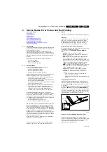
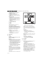
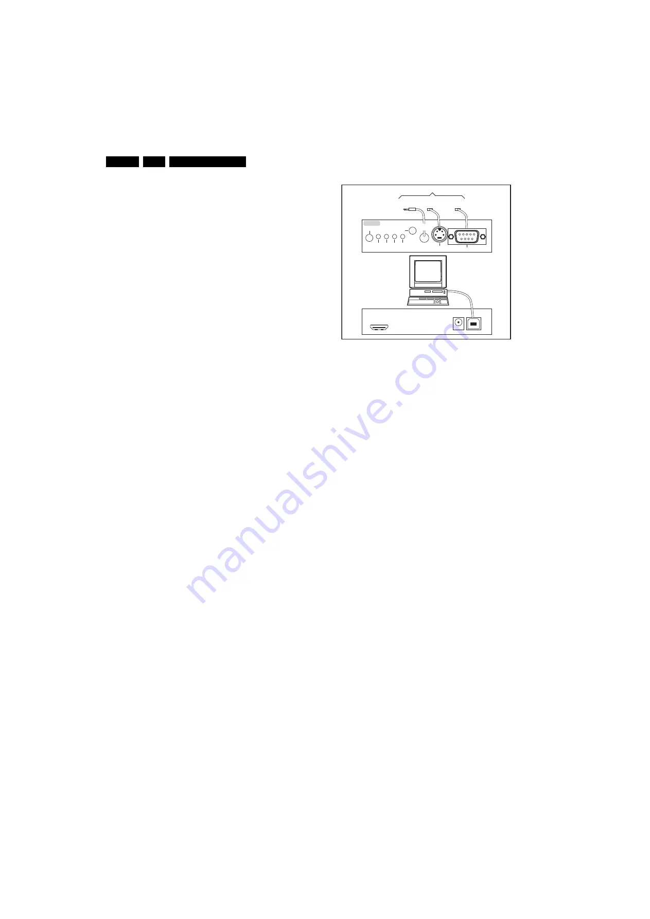
Figure 5-3 ComPair II interface connection
Caution:
It is compulsory to connect the TV to the PC as
shown in the picture above (with the ComPair interface in
between), as the ComPair interface acts as a level shifter. If
one connects the TV directly to the PC (via UART), ICs will be
blown!
How to Order
ComPair II order codes:
•
ComPair II interface: 3122 785 91020.
•
ComPair UART interface cable: 3138 188 75051.
•
Program software can be downloaded from the Philips
Service web portal.
Note:
For this chassis, no new database is made as ComPair
will be phased out.
In addition, you can use the ComPair box as level shifter for
UART logging.
Additional cables for VCOM Alignment
•
ComPair/I
2
C interface cable: 3122 785 90004.
•
ComPair/VGA adapter cable: 9965 100 09269.
5.4
Error Codes
5.4.1
Introduction
Error codes are required to indicate failures in the TV set. In
principle a unique error code is available for every:
•
Activated (SW) protection.
•
Failing I
2
C device.
•
General I
2
C error.
The last five errors, stored in the NVM, are shown in the
Service menu’s. This is called the error buffer.
The error code buffer contains all errors detected since the last
time the buffer was erased. The buffer is written from left to
right. When an error occurs that is not yet in the error code
buffer, it is displayed at the left side and all other errors shift one
position to the right.
An error will be added to the buffer if this error differs from any
error in the buffer. The last found error is displayed on the left.
An error with a designated error code
never
leads to a
deadlock situation. It must always be diagnosable (e.g. error
buffer via OSD or blinking LED or via ComPair).
In case a failure identified by an error code automatically
results in other error codes (cause and effect), only the error
code of the MAIN failure is displayed.
10000_0
3
6_090121.ep
s
09111
8
TO
UART
S
ERVICE
CONNECTOR
TO
UART
S
ERVICE
CONNECTOR
TO
I2C
S
ERVICE
CONNECTOR
TO TV
PC
HDMI
I
2
C only
Option
a
l power
5V DC
ComP
a
ir II Developed
b
y Philip
s
Br
u
gge
RC o
u
t
RC in
Option
a
l
S
witch
Power
Mode
Link/
Activity
I
2
C
ComP
a
ir II
M
u
lti
f
u
nction
R
S
2
3
2 /UART

