OPERATING INSTRUCTIONS
EN
Translation of the Original
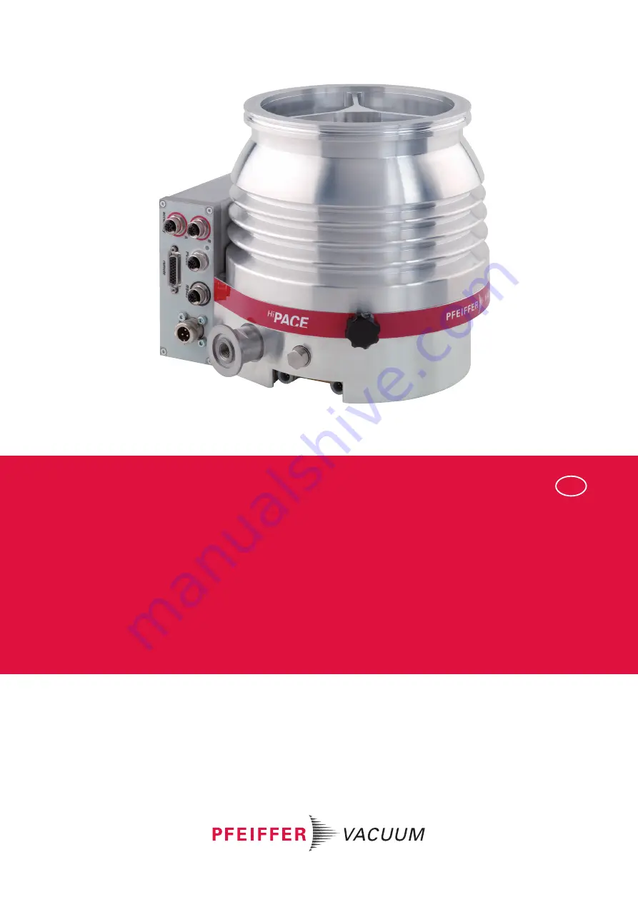
HIPACE 700
Turbopump
Страница 1: ...OPERATING INSTRUCTIONS EN Translation of the Original HIPACE 700 Turbopump...
Страница 2: ...fer vacuum de Further operating instructions from Pfeiffer Vacuum can be found in the Download Center on our website Disclaimer of liability These operating instructions describe all models and varian...
Страница 3: ...ansport 19 4 2 Storage 19 5 Installation 20 5 1 Preparatory work 20 5 2 Connecting the high vacuum side 20 5 2 1 Designing the counter flange 20 5 2 2 Considering earthquake protection 21 5 2 3 Using...
Страница 4: ...e intervals and responsibilities 39 7 3 Replacing the operating fluid reservoir 39 7 4 Replacing the electronic drive unit 41 7 5 Confirming the rotation speed specification 42 8 Decommissioning 43 8...
Страница 5: ...water connection 29 Tbl 9 Pre set accessory connections to electronic drive unit TC 400 31 Tbl 10 Factory setting of the electronic drive unit when delivered 34 Tbl 11 Behavior and meaning of the LEDs...
Страница 6: ...apped hole 25 Fig 11 Flange connection ISO F stud screw and through hole 26 Fig 12 Flange connection CF F hexagon head screw and through hole 26 Fig 13 Flange connection CF F stud screw and tapped hol...
Страница 7: ...T 0302 BN Operating instructions Electronic drive unit TC 400 DN DeviceNet PT 0352 BN Operating instructions Electronic drive unit TC 400 EC EtherCat PT 0452 BN Declaration of conformity A component o...
Страница 8: ...the stickers on the product along with their meaning C US T V Rheinland Oil S N Mod HiPace 700 H PM P05 750 P N n f Mass Made in Germany 2018 03 PM 143 452 T 49200 1 min 820 Hz 17 4 kg D 35614 Asslar...
Страница 9: ...r control and monitoring of pump parameters HV High vacuum flange high vacuum side ISO Flange Connector in accordance with ISO 1609 and ISO 2861 LED Illuminating diode PE Earthed conductor protective...
Страница 10: ...E Danger of property damage Notice is used to address practices not related to physical injury Instructions on avoiding property damage Notes tips or examples indicate important information on the pro...
Страница 11: ...of cuts on moving sharp edged parts when reaching into the open high vacuum flange With the high vacuum flange open access to sharp edged parts is possible A manual rotation of the rotor increases the...
Страница 12: ...ion Make sure that high process related over pressures cannot directly enter the vacuum pump CAUTION Risk of injuries due to contact with vacuum when venting While venting the vacuum pump there is a r...
Страница 13: ...e is a risk of electric body contact and as a result the destruction of electronic components Never disconnect the turbopump and electronic drive unit from each other if power is still con nected or i...
Страница 14: ...personnel aware of dangers posed by this product Every person who is involved in the installation operation or maintenance of the product must read understand and adhere to the safety related parts o...
Страница 15: ...Proper use Use the turbopump only for generating vacuum Use the turbopump only in combination with a suitable backing pump that can deliver up to the required maximum fore vacuum pressure Use the tur...
Страница 16: ...ausing of hazardous operating conditions by a presetting on the electronic drive unit that is contrary to the process Use of accessories or spare parts that are not listed in these instructions Safety...
Страница 17: ...unit 6 Fore vacuum connection DN 25 ISO KF 14 Pump housing aluminum 7 LED operating mode display 15 Sealing gas connection 8 Pump base 16 Protective cover for the high vacuum connection 3 1 1 Cooling...
Страница 18: ...ID no 000021320 3 3 1 Product types The product designation of Pfeiffer Vacuum turbopumps from the HiPace series is composed of the family name the size which is based on the pumping speed of the vacu...
Страница 19: ...e weight specified on the rating plate Where possible always transport or ship the turbopump in its original packaging Always carry the turbopump with both hands Remove the protective cover only immed...
Страница 20: ...ve gloves during installation Do not start the turbopump with open vacuum connections Always carry out the mechanical installation before electrical connection Prevent access to the high vacuum connec...
Страница 21: ...l in all operating states in rela tion to the engagement depth of the fixing screws 170 N mm2 at 2 5 d 270 N mm2 at 1 5 d Maximum permissible surrounding magnetic field 6 0 mT Maximum permissible irra...
Страница 22: ...ith the vibration compensator in the event of a malfunction Sudden jamming of the rotor generates high destructive torques in accordance with ISO 27892 When using a vibration compensator this will pro...
Страница 23: ...may occur in the event of sudden blockage of the rotor despite correct installation Leak tightness of the flange connection however is not jeopardized in this regard Required tools Wrench WAF 15 Cali...
Страница 24: ...d components for the turbopump 6 Screw the hexagon head screws into the tapped holes Observe the minimum tensile strength of the flange material and the screw depth 7 Fasten the hexagon head screws cr...
Страница 25: ...ation with ISO F flange are Hexagon head screw and tapped hole Stud screw with tapped hole Stud screw with through hole Required tools Hexagonal wrench 15 WAF Calibrated torque wrench tightening facto...
Страница 26: ...pump with collar flange snap ring and centering ring to the counter flange accord ing to the figure 3 Use for all prescribed components for the turbopump 4 Fasten the screw connections cross wise in 3...
Страница 27: ...3 If used Insert the protective screen or splinter shield with clamping lugs downwards in the turbo pump high vacuum flange 4 Place the seal exactly in the hollow 5 Connect the flange with the compone...
Страница 28: ...a suitable vacuum pump or a pumping station from the Pfeiffer Vacuum range In this case the backing pump is also controlled directly via the turbopump electronic drive unit interfaces e g relay box or...
Страница 29: ...ter cooling at ambient temperatures 35 C Parameter Cooling water Appearance filtered mechanically clear visually clear no turbidity no sediment free from grease and oil pH value 7 to 9 Carbonate hardn...
Страница 30: ...accessories can be found online The following accessories are not included in the scope of supply Electronic drive unit TC 400 accessory connection The electronic drive unit of the turbopump offers sp...
Страница 31: ...accessory Note the existing configuration of existing connections Use the Pfeiffer Vacuum display and control unit DCU 002 or a DCU with integrated power supply pack 5 6 Connecting the electrical sup...
Страница 32: ...ve There is a danger to life from electric shock when making contact with live components Always keep the mains connection freely accessible so you can disconnect it at any time WARNING Danger of cut...
Страница 33: ...ting cable into the connection DCin on the electronic drive unit and close the bayonet lock 5 Insert the connecting cable into the connection DCout on the power supply pack and close the bayonet lock...
Страница 34: ...leads to the destruction of the tur bopump Make sure that the gas mode is set correctly by P 027 in the electronic drive unit Consult Pfeiffer Vacuum before you use gases with higher molecular masses...
Страница 35: ...function connection remote Remote control is available via the 26 pole D sub connector with the remote designation on the elec tronic drive unit The accessible individual functions are mapped to PLC...
Страница 36: ...g the vacuum pump or for optimizing the process gener ates very high temperatures on surfaces that can be touched There is a risk of burning If necessary set up a contact guard If necessary apply the...
Страница 37: ...set In order to avoid switching off the turbopump the electronic drive unit already reduces the power consumption in case of exceeding the warning threshold for excess temperature Examples are an imp...
Страница 38: ...m venting valve is an optional accessory for installation on the turbopump The venting valve is normally closed Control is via the turbopump electronic drive unit and configura tion of parameters P 01...
Страница 39: ...ve equipment 7 2 Maintenance intervals and responsibilities Recommendations for performing maintenance measures 1 Clean the turbopump exterior with a lint free cloth and a little isopropanol 2 Replace...
Страница 40: ...ge 38 4 Interrupt the electric supply 5 Remove all cables from the electronic drive unit 6 If dismantling the turbopump from the system Close all openings with the original protective covers and screw...
Страница 41: ...398 Wait until the turbopump comes to a standstill rotation speed f 0 NOTICE Property damage from electrostatic discharge Neglecting the electrostatic hazard for electronic components results in their...
Страница 42: ...ared The manual confirmation of the nominal rotation speed is part of a redun dant safety system as a measure for preventing excess rotation speed HiPace Nominal rotation speed 10 30 60 80 1500 Hz 300...
Страница 43: ...ed temperature range 9 In rooms with humid or aggressive atmospheres Hermetically seal the turbopump together with a drying agent in a plastic bag 8 2 Recommissioning NOTICE Risk of damage to the turb...
Страница 44: ...risk to health from contact with these poisonous substances Illegal disposal of toxic sub stances causes environmental damage Take suitable safety precautions and prevent health hazards or environmen...
Страница 45: ...to poisoning Keep masses connected to the turbopump as low as possible Use flexible lines to connect to the turbopump where necessary WARNING Risk of injury caused by the turbopump breaking away with...
Страница 46: ...nical data 2 Check that the backup pump is working Leakage on the turbo pump 1 Carry out leak detection 2 Check seals and flange connections 3 Eliminate leaks Gas throughput too high 1 Reduce the proc...
Страница 47: ...ectronic drive unit illuminates Group error 1 Reset the malfunction by switching the current supply off and on 2 Reset the malfunction with V on pin 13 on the remote connection 3 Set the parameter P 0...
Страница 48: ...and addresses can be found on our website in the Pfeiff er Vacuum Service section Advice on the optimum solution is available from your Pfeiffer Vacuum contact partner For quick and smooth handling of...
Страница 49: ...ontainers e Observe the applicable transport conditions ERKL RUNG KONTAMINIERUNG 6 Affix the declaration of contamination to the outside of the packag ing 7 Then send your product to your local Servic...
Страница 50: ...ion Designation Order number Note Pieces Quanti ty 1 Electronic drive unit TC 400 refer to the rating plate depending on the connection panel 1 2 Operating fluid reser voir PM 143 452 T incl capillary...
Страница 51: ...as valve or a sealing gas throttle without control Air cooling For processes with low gas throughputs and good fore vacuum pressure air cooling can be used inde pendently of a water supply Automatic c...
Страница 52: ...e M12 on M12 PM 061 747 T Y connector shielded M12 for accessories P 4723 013 Y Connector M12 to RS 485 P 4723 010 USB Converter to RS 485 Interface PM 061 207 T Venting Valve Shielded 24 V DC PM Z01...
Страница 53: ...ter temperature 25 C Integral leakage rate with 100 helium concentration 10 s measurement duration Sound pressure level at distance to vacuum pump 1 m mbar bar Pa hPa kPa Torr mm Hg mbar 1 1 10 3 100...
Страница 54: ...1 hPa 11 hPa 11 hPa Rotation speed 2 49200 rpm 49200 rpm 49200 rpm Rotation speed variable 60 100 60 100 60 100 Power characteristic line in gas mode 0 vertex C 200 49200 W min 1 200 49200 W min 1 200...
Страница 55: ...nical data for HiPace 700 48 V Classification advanced HiPace 700 with TC 400 HiPace 700 with TC 400 HiPace 700 with TC 400 Order number PM P03 930 PM P03 931 PM P03 932 Flange in DN 160 ISO K DN 160...
Страница 56: ...W min 1 250 46800 W min 1 250 46800 W min 1 Operating voltage DC 24 V 24 V 24 V Power consumption max 300 W 300 W 300 W Input voltage tolerance 5 5 5 Current consumption max Run up time 4 min 4 min 4...
Страница 57: ...l data for HiPace 700 24 V 13 3 Dimensions Dimensions in mm 148 179 203 5 212 181 145 5 HV DN 160 ISO K M8 6x 150 208 45 45 16 7 30 130 1 1 7 59 VV DN 25 ISO KF G 1 4 8 131 Fig 22 HiPace 700 TC 400 DN...
Страница 58: ...148 179 5 203 5 212 181 145 5 HV DN 160 ISO F M8 6x 208 45 45 16 7 30 130 1 1 7 59 VV DN 25 ISO KF G 1 4 8 131 150 Fig 24 HiPace 700 TC 400 DN 160 ISO F Technical data and dimensions 58 60...
Страница 59: ...presentative for the compilation of technical documents is Mr Hel mut Bernhardt Pfeiffer Vacuum GmbH Berliner Stra e 43 35614 A lar Germany Turbopump HiPace 700 Harmonized standards and applied nation...
Страница 60: ...PT0209 ed K Date 1903 P N PT0209BEN...