OPERATING INSTRUCTIONS
EN
Translation of the Original
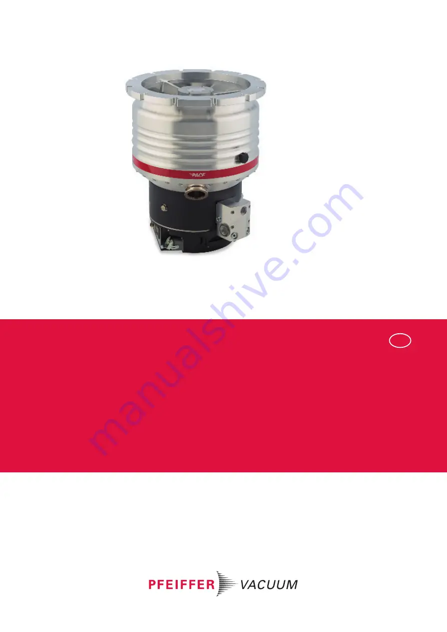
HIPACE 2300
Turbopump
Страница 1: ...OPERATING INSTRUCTIONS EN Translation of the Original HIPACE 2300 Turbopump...
Страница 2: ...fer vacuum de Further operating instructions from Pfeiffer Vacuum can be found in the Download Center on our website Disclaimer of liability These operating instructions describe all models and varian...
Страница 3: ...g 21 3 1 3 Drive 21 3 2 Scope of delivery 21 3 3 Identifying the product 22 3 3 1 Product types 22 3 3 2 Product features 22 4 Transportation and Storage 23 4 1 Transport 23 4 1 1 Transport in vertica...
Страница 4: ...2 Venting 46 7 Maintenance 47 7 1 General maintenance information 47 7 2 Maintenance intervals and responsibilities 47 7 3 Changing the operating fluid 48 7 3 1 Draining the operating fluid 48 7 3 2...
Страница 5: ...ection 38 Tbl 11 Factory pre set accessory connections on the electronic drive unit 39 Tbl 12 Terminal lay out of the power supply connector 41 Tbl 13 Preconfigured settings for turbopumps when delive...
Страница 6: ...CF F hexagon head screw and through hole 34 Fig 18 Flange connection CF F stud screw and tapped hole 34 Fig 19 Flange connection CF F stud screw and through hole 34 Fig 20 The position of the filler s...
Страница 7: ...ing instructions Electronic drive unit TC 1200 E74 ac cording to Semi E74 PT 0303 BN Operating instructions Electronic drive unit TC 1200 DN Device Net PT 0353 BN Operating instructions Electronic dri...
Страница 8: ...tes an action with multiple necessary steps 1 Step 1 2 Step 2 3 1 3 2 Pictographs Pictographs used in the document indicate useful information Note Tip 1 3 3 Stickers on the product This section descr...
Страница 9: ...G WATER IN max 6 bar 90 psi Cooling water connection This sticker indicates the position and conditions for the cooling water supply of the turbopump COOLING WATER OUT Cooling water connection This st...
Страница 10: ...it Pfeiffer Vacuum display and control unit DN Nominal diameter as size description EMS Emergency Stop f Rotation speed value of a vacuum pump frequency in rpm or Hz HPU Handheld Programming Unit Aid...
Страница 11: ...iceNet is a trademark of Open DeviceNet Vendor Association Inc Profibus is a trademark of Profibus Nutzerorganisation e V Profibus is a registered trade name of Profibus Nutzerorganisation e V Profibu...
Страница 12: ...perty Notes tips or examples indicate important information about the product or about this document 2 2 Safety instructions All safety instructions in this document are based on the results of the ri...
Страница 13: ...urring torques Before installing a vibration compensator you must first of all contact Pfeiffer Vacuum WARNING Danger to life from poisoning where toxic process media leak from damaged con nections Su...
Страница 14: ...d in the exposed high vacuum flange Only connect mating plugs after the mechanical installation Only switch on the vacuum pump immediately prior to operation WARNING Risk of serious injury from oscill...
Страница 15: ...ion due to over pressure Gas entry with very high over pressure results in destruction of the vacuum pump There is a risk of serious injury due to ejected objects Never exceed the permissible 1500 hPa...
Страница 16: ...ut maintenance work Wear protective equipment WARNING Risk of cuts on moving sharp edged parts when reaching into the open high vac uum connection Incorrect handling of the turbopump before maintenanc...
Страница 17: ...O 27892 When using a vibration compensator this will probably lead to the turbopump being sheared off in use The energy that this would release could throw the entire turbo pump or shattered pieces fr...
Страница 18: ...s stopped com pletely rotation speed f 0 Never put the device into operation with the high vacuum connection open Keep lines and cables away from hot surfaces 70 C Never fill or operate the unit with...
Страница 19: ...operation of the vacuum pump in an impermissible spatial posi tion Establishing the voltage supply without correct installation Installing the pump with unspecified mounting material Pumping explosive...
Страница 20: ...documentation In addition these individuals must be familiar with applicable safety regulations and laws as well as the other standards guidelines and laws referred to in this documentation The above...
Страница 21: ...unit TC 1200 6 Venting screw 12 Ground terminal 3 1 1 Cooling Water cooling The electronic drive unit automatically regulates the drive power down in the event of exces sive temperatures 3 1 2 Rotor...
Страница 22: ...duct designation of Pfeiffer Vacuum turbopumps from the HiPace series is composed of the family name the size which is based on the pumping speed of the vacuum pump and if required an additional featu...
Страница 23: ...he labels relating to the valid spatial position of the vacuum pump Observe the property labels on the type plate Drain off the operating fluid before moving or transporting the vacuum pump Only fill...
Страница 24: ...0 max Fig 3 Slinging points for vertical transport of the turbopump without packaging Instructions for vertical transport 2 eye bolts are included in the shipment and are firmly bolted to the turbopum...
Страница 25: ...the eye bolt following transport and installation as required Keep the eye bolt for future use 4 2 Storage We recommend Pfeiffer Vacuum recommends storing the products in their original transport pac...
Страница 26: ...the turbopump with open vacuum connections Always carry out the mechanical installation before electrical connection Prevent access to the high vacuum connection of the turbopump from the operator si...
Страница 27: ...event of a burst1 16000 Nm Maximum permissible axial load on the high vacuum flange2 2000 N equivalent to 200 kg Flatness 0 05 mm Minimum tensile strength of the flange material in all operating state...
Страница 28: ...suitable for use on vibration sensitive systems WARNING Risk of injury caused by the turbopump breaking away with the vibration compensa tor in the event of a malfunction Sudden jamming of the rotor...
Страница 29: ...spatial position of the vacuum pump Observe the property labels on the type plate Drain off the operating fluid before moving or transporting the vacuum pump Only fill the vacuum pump with operating f...
Страница 30: ...ISO K to ISO F bracket screws Connection with bracket screw 1 For the connection of the turbopump use only the approved mounting kits from Pfeiff er Vacuum 2 Connect the flange with the components of...
Страница 31: ...nd tapped hole Connection of the stud screw and tapped hole 1 For the connection of the turbopump use only the approved mounting kits from Pfeiffer Vacuum 2 Screw in the required number of stud screws...
Страница 32: ...mp use only the approved mounting kits from Pfeiff er Vacuum 2 Attach the turbopump with centering ring to the counter flange according to the figure 3 Use all prescribed components for the turbopump...
Страница 33: ...the approved mounting kits from Pfeiff er Vacuum 2 Attach the turbopump with collar flange snap ring and centering ring to the counter flange according to the figure 3 Use all prescribed components f...
Страница 34: ...urbopump use only the approved mounting kits from Pfeiffer Vacuum 2 Screw in the required number of stud screws with the shorter end in the holes on the counter flange 3 If used Insert the protective...
Страница 35: ...ng with operating fluid The operating fluid filling quantity depends on the selected spatial position of the turbo pump The filler screws are located at clearly marked positions on both sides of the o...
Страница 36: ...en twisting of the turbopump in the event of a fault causes fittings to accelerate There is the risk of damaging on site connections e g fore vacuum line and resulting leaks This results in leakage of...
Страница 37: ...ract the backflow of operating fluids or condensate from the fore vacuum area 4 Observe the information in the operating instructions of the backup pump or pumping station when connecting and operatin...
Страница 38: ...re see Technical data Cooling water flow see Technical data Cooling water pressure max 6000 hPa Tbl 9 Requirements on the cooling water composition The HiPace 2300 turbopumps use water cooling as stan...
Страница 39: ...feiffer Vacuum display and control units or a PC You can find more detailed information in the Electronic drive unit TC 1200 operating manual Electronic drive unit connection Accessory connection Y co...
Страница 40: ...nnection leads are voltage free Make sure that electrical installations are only carried out by qualified electricians Provide adequate grounding for the device After connection work carry out an eart...
Страница 41: ...rt up The use of mating plugs of the electronic drive unit accessories enables the automatic run up of the vacuum pump as soon the power is turned on Attaching mating plugs before or during the instal...
Страница 42: ...orrectly by P 027 in the electronic drive unit Consult Pfeiffer Vacuum before you use gases with higher molecular masses 80 Important settings and function related variables are factory programmed int...
Страница 43: ...6 2 2 Operation via connection E74 Operation is possible via the 15 pole D sub connection with the E74 designation on the electronic drive unit Besides the signals defined in the Directive SEMI E74 03...
Страница 44: ...itional equipment for heating the vacuum pump or for optimizing the process generates very high temperatures on surfaces that can be touched There is a risk of burn ing If necessary set up a contact g...
Страница 45: ...ror messages are immutably stored in the electronic drive unit For information purposes var ious status requests are set up in the parameter set In order to avoid switching off the turbopump the elect...
Страница 46: ...ximum 3 Wait for pressure equalization to atmospheric pressure in the vacuum system 4 Close the venting screw again Use a Pfeiffer Vacuum venting valve The Pfeiffer Vacuum venting valve is an optional...
Страница 47: ...equipment WARNING Risk of cuts on moving sharp edged parts when reaching into the open high vac uum connection Incorrect handling of the turbopump before maintenance work results in hazardous situa ti...
Страница 48: ...s toxic vapors Danger of poisoning if inhaled Observe the application instructions and precautions Do not allow tobacco products to come into contact with the operating fluid You can find the safety d...
Страница 49: ...fluid The operating fluid filling quantity depends on the selected spatial position of the turbo pump The filler screws are located at clearly marked positions on both sides of the operat ing fluid p...
Страница 50: ...it due to im proper disconnection of components Even after the mains power is switched off the turbopump continues to deliver electrical energy during its run down period If the turbopump and electron...
Страница 51: ...nt the vacuum system to atmospheric pressure see chapter Venting page 46 4 Interrupt the electric supply 5 Remove all cables from the electronic drive unit 6 If dismantling the turbopump from the syst...
Страница 52: ...the groove in the pump base 2 Line up the new electronic drive unit with the straight edge of the operating fluid pump 3 Carefully place the electronic drive unit on the connecting plug of the turbopu...
Страница 53: ...used the refer ence set value of the nominal rotation speed is cleared The manual confirmation of the nomi nal rotation speed is part of a redundant safety system as a measure for preventing excess r...
Страница 54: ...tically seal the turbopump to gether with a drying agent in a plastic bag Vorgehensweise f r ein l ngeres Stillsetzen der Turbopumpe 1 Jahr 1 Bauen Sie die Turbopumpe ggf aus dem Vakuumsystem aus 2 La...
Страница 55: ...Pfeiffer Vacuum Service to completely clean the turbopump 4 Observe the total running time of the turbopump and if necessary arrange for Pfeiff er Vacuum Service to replace the bearing 5 Change the t...
Страница 56: ...must be disposed of in accordance with the applicable regulations relating to environmental protection and human health with a view to reducing natural resource wastage and preventing pollution 9 1 G...
Страница 57: ...jamming of the rotor generates high destructive torques in accordance with ISO 27892 When using a vibration compensator this will probably lead to the turbopump being sheared off in use The energy tha...
Страница 58: ...the interface RS 485 to 1 ON Voltage drop in the ca ble is too high Check the connection cable Use a suitable connection cable Turbopump fails to reach the nominal rotation speed within the set run u...
Страница 59: ...electronic drive unit illuminates Group error Reset the malfunction by switching the cur rent supply off and on Reset the malfunction with V on pin 13 on the remote connection Set the parameter P 009...
Страница 60: ...bility You can find more detailed information and addresses on our homepage in the Pfeiffer Vacuum Service section You can obtain advice on the optimal solution for you from your Pfeiffer Vacuum rep r...
Страница 61: ...oduct in suitable stable transport containers only e Maintain applicable transport conditions ERKL RUNG KONTAMINIERUNG 6 Attach the contamination declaration to the outside of the packaging 7 Now send...
Страница 62: ...el 1 2 Mating plug remote PM 061 378 X with solder tags 1 3 Supply socket HAN 3 PM 061 200 T 1 4 Sealing gas valve 17 5 20 sccm PM Z01 313 1 5 Syringe 50 ml PM 006 915 U 1 6 Operating fluid F3 50 ml P...
Страница 63: ...sealing gas valve or a sealing gas throttle without control Air cooling For processes with low gas throughputs and good fore vacuum pressure air cooling can be used independently of a water supply Au...
Страница 64: ...r DN 250 ISO F including coated centering ring splinter shield stud screws PM 016 486 T Mounting kit for DN 250 ISO F including coated centering ring protective screen stud screws PM 016 487 T Vibrati...
Страница 65: ...ad DN 16 ISO KF G 1 8 PM 016 780 T Push in fitting for 6 mm tube G 1 8 PM 016 781 T Push in fitting for 8 mm tube G 1 8 PM 016 782 T Hose nozzle for 9 mm hose G 1 8 PM 016 783 T TTV 001 Drier for vent...
Страница 66: ...100 helium concentration 10 s measurement duration Sound pressure level at distance to vacuum pump 1 m mbar bar Pa hPa kPa Torr mm Hg mbar 1 1 10 3 100 1 0 1 0 75 bar 1000 1 1 105 1000 100 750 Pa 0 01...
Страница 67: ...105 3 105 Compression ratio for N2 1 108 1 108 1 108 Performance curve in gas mode 0 vertex C 517 31500 W min 1 517 31500 W min 1 518 31500 W min 1 Performance curve in gas mode 0 vertex D 682 25200 W...
Страница 68: ...st 1 10 7 hPa 1 10 7 hPa 5 10 10 hPa Pumping speed for Ar 1800 l s 1800 l s 1800 l s Pumping speed for H2 1850 l s 1850 l s 1850 l s Pumping speed for He 2000 l s 2000 l s 2000 l s Pumping speed for N...
Страница 69: ...on fre quency range 50 60 Hz 50 60 Hz 50 60 Hz Power consumption max 1350 VA 1350 VA 1350 VA Current max 10 A 10 A 10 A Cooling water connection G 1 4 G 1 4 G 1 4 Cooling method Water Water Water Cool...
Страница 70: ...mance curve in gas mode 0 vertex D 682 25200 W min 1 682 25200 W min 1 584 10560 W min 1 Performance curve in gas mode 1 vertex A 690 31500 W min 1 690 31500 W min 1 575 31500 W min 1 Performance curv...
Страница 71: ...s 1850 l s Pumping speed for He 2000 l s 2000 l s 2000 l s Pumping speed for N2 1900 l s 1900 l s 1900 l s Gas throughput at final rotation speed for Ar 8 hPa l s 8 hPa l s 8 hPa l s Gas throughput a...
Страница 72: ...Integrated electron ic drive unit Integrated elec tronic drive unit Electronic drive unit TC 1200 TC 1200 TC 1200 Mains connection volt age range 90 265 V AC 90 265 V AC 90 265 V AC Mains connection f...
Страница 73: ...51 4 3 150 G 1 8 DN 40 ISO KF 238 400 229 167 4 0 G 1 8 48 DN 250 ISO F 311 27 G 1 4 245 68 4 0 170 335 285 Fig 33 Dimensions HiPace 2300 and HiPace 2300 C DN 250 ISO F Fig 34 Dimensions HiPace 2300 a...
Страница 74: ...ions HiPace 2300 U and HiPace 2300 UC DN 250 ISO K Fig 36 Dimensions HiPace 2300 U and HiPace 2300 UC DN 250 ISO F Fig 37 Dimensions HiPace 2300 U and HiPace 2300 UC DN 250 CF F Technical data and dim...
Страница 75: ...of certain hazardous substances delegated directive 2015 863 EU Harmonized standards and applied national standards and specifications DIN EN ISO 12100 2011 ISO 21360 1 2016 DIN EN 1012 2 2011 ISO 21...
Страница 76: ...PT0567 ed C Date 2112 P N PT0567BEN...