B
G
5139
E
N
/ A
(2012-11)
A P A S S I O N F O R P E R F E C T I O N
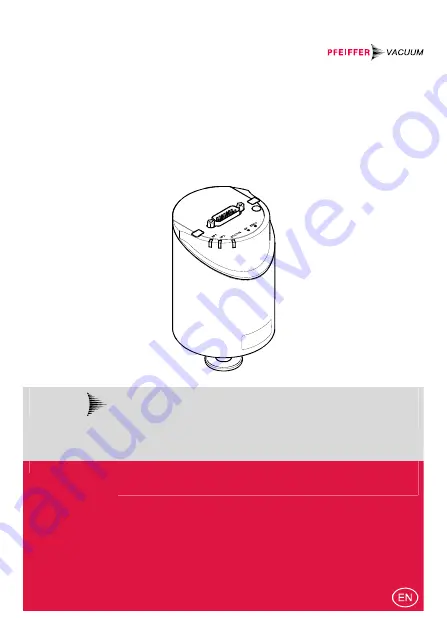
CCR 371 … CCR 375
Ceramic Capacitance Gauge
Operating Instructions
Страница 1: ...BG 5139 BEN A 2012 11 A P A S S I O N F O R P E R F E C T I O N CCR 371 CCR 375 Ceramic Capacitance Gauge Operating Instructions...
Страница 2: ...ion In all communications with Pfeiffer Vacuum please specify the information given on the product nameplate For convenient re ference copy that information into the space provided below Pfeiffer Vacu...
Страница 3: ...373 PT R28 123 8 VCR 10 3 10 F S 1 33 10 1 1 333 22 F S 10 3 13 3 F S PT R28 130 Rohr PT R28 131 DN 16 ISO KF PT R28 132 DN 16 CF R CCR 374 PT R28 133 8 VCR 10 4 1 F S 1 33 10 2 133 322 F S 10 4 1 3...
Страница 4: ...ut signal is independent of the gas type Very accurate pressure measurement is achieved by heating the sensor to a constant temperature of 45 C which results in a com pensation of changes in the ambie...
Страница 5: ...Warranty 7 2 Technical Data 8 3 Installation 13 3 1 Vacuum Connection 13 3 2 Power Connection 16 4 Operation 19 4 1 Status Indication 19 4 2 Zeroing the Gauge 20 4 3 Switching Functions 25 4 4 Activat...
Страница 6: ...ntal damage Caution Information on correct handling or use Disregard can lead to malfunctions or minor equipment damage Notice Labeling 1 2 Personnel Qualifications Skilled personnel All work describe...
Страница 7: ...regulations and take the necessary precautions when handling contamin ated parts Communicate the safety instructions to all other users 1 4 Liability and Warranty Pfeiffer Vacuum assumes no liability...
Страница 8: ...gnal Voltage range 0 10 V Measuring range 5 10 24 V limited to 10 24 V Relationship voltage pressure linear Output impedance 0 short circuit proof Loaded impedance 10 k Response time 2 PT R28 100 PT R...
Страница 9: ...Supply DANGER The gauge may only be connected to power sup plies instruments or control devices that conform to the requirements of a grounded protective extra low voltage SELV and limited power sour...
Страница 10: ...tor cross sections are required Rcable 1 0 Grounding concept Power Connection Materials exposed to vacuum ceramics Al2O3 99 5 stainless steel AISI 316L Internal volume 4 2 cm3 Admissible pressure abso...
Страница 11: ...BG 5139 BEN A 2012 11 11 Dimensions mm 8 VCR female DN 16 ISO KF 82 110 4 DN 16 CF R OD 31 5 3 8 13 Weight 837 897 g...
Страница 12: ...S 1 1 F S Pressure p Measuring signal Uout V 0 0 F S p Uout 10 V p F S Conversion Torr Pascal Torr mbar 3 Pa 3 c 1 00 1013 25 760 1 3332 101325 760 133 3224 Example Gauge with 10 Torr F S Measurement...
Страница 13: ...and harm caused by escaping process gases can result if clamps are opened while the vacuum system is pressurized Do not open any clamps while the vacuum system is pressurized Use the type clamps whic...
Страница 14: ...requirement For gauges with a KF flange use a conductive metallic clamping ring For gauges with a tube take appropriate measures to fulfill this requirement Caution Caution vacuum component Dirt and d...
Страница 15: ...into the measuring chamber preferably choose a horizontal to upright posi tion If adjustment should be possible after the gauge has been installed be sure to install it so that the but tons can be ac...
Страница 16: ...measurement signal For optimum signal quality please do observe the following notes Use an overall metal braided shielded cable The connector must have a metal case Connect the cable shield to ground...
Страница 17: ...rement signal or thresholds SP1 2 Pin 3 Status Pin 5 Supply common Pin 6 Supply 15 V Pin 7 11 Supply 14 30 V or 15 V Pin 8 9 Relay SP2 closing contact Pin 10 Gauge identification or Remote Zero Adjust...
Страница 18: ...18 BG 5139 BEN A 2012 11 Connect the sensor cable to the gauge and secure it using the lock screw Connect the sensor cable to the controller...
Страница 19: ...ecommend setting its signal filter to fast 4 1 Status Indication For factory setting only LED LED status Meaning STATUS off no supply voltage lit solid green measurement mode blinking green short blin...
Страница 20: ...ro operate the gauge under the same con stant ambient conditions and in the same mounting orientation as normally The output signal measuring signal is depending on the moun ting orientation The signa...
Страница 21: ...a pressure according to the table below F S Recommended final pressure for zero adjustment 1000 Torr 100 Torr 10 Torr 1 Torr 0 1 Torr 5 10 2 Torr 5 10 3 Torr 5 10 4 Torr 5 10 5 Torr 5 10 6 Torr 6 65 1...
Страница 22: ...LED blinks until the adjustment duration 8 s is completed max 1 1 mm Press the button briefly After zero adjustment the gauge automatically returns to measurement mode The STATUS LED lit The STATUS LE...
Страница 23: ...the characteristic curve in order to compensate for the offset of the measuring system or obtain a slightly positive zero for a 0 10 V AD converter The offset should not exceed 2 of the F S 200 mV At...
Страница 24: ...sponding output signal is delayed by about 1 s max 1 1 mm Keep the button depressed Push the ZERO button again Fine adjustment within 0 3 s the zero adjustment value changes by one unit push ZERO butt...
Страница 25: ...output at the D Sub connector instead of the measurement signal 17 and can be measured with a voltmeter after the SP button is pressed or can be read written via the RS232C interface If the pressure...
Страница 26: ...the cor responding threshold value is output instead This can cause malfunctions Push the SP button only if you are sure that no damages can arise from a malfunction Adjusting Setpoint 1 Push the SP...
Страница 27: ...max 1 1 mm Keep the button depressed Push the ZERO button again Fine adjustment within 0 3 s the zero adjustment value changes by one unit Change of direction within 3 5 s the zero adjustment changes...
Страница 28: ...4 4 Activating the Factory Setting Factory Reset All user defined parameters e g zero filter are restored to their default values Loading of the default parameters is irreversible Loading the default...
Страница 29: ...d parts can be detrimental to health and environment Before beginning to work find out whether any parts are contaminated Adhere to the relevant regulations and take the necessary precautions when han...
Страница 30: ...he lock screw and disconnect the sensor cable Remove the gauge from the vacuum system and install the protective lid 6 Maintenance Repair Under clean operating conditions the product requires no main...
Страница 31: ...d pre ferably be free of harmful substances Adhere to the forwarding regulations of all involved countries and forwarding companies and enclose a duly completed declaration of contamination Form under...
Страница 32: ...d electric components operating fluids etc can be detrimen tal to the environment Dispose of such substances in accordance with the relevant local regulations Separating the components After disassemb...
Страница 33: ...0 01 1 10 3 7 5 10 3 hPa 1 1 10 3 100 1 0 1 0 75 kPa 10 0 01 1 10 3 10 1 7 5 Torr mm HG 1 332 1 332 10 3 133 32 1 3332 0 1332 1 1 Pa 1 N m 2 ETL Certification 3103457 ETL LISTED The products CCR 371...
Страница 34: ...e CCR 371 CCR 375 Standards Harmonized and international national standards and specifi cations EN 61000 6 2 2005 EMC generic immunity standard EN 61000 6 3 2007 EMC generic emission standard EN 61010...
Страница 35: ...BG 5139 BEN A 2012 11 35 Notes...
Страница 36: ...onent to complex systems We are the only supplier of vacuum technology that provides a complete product portfolio Benefit from our know how and our portfolio of training opportunities We can support y...