PA
0409 BEN/A
(
1901
)
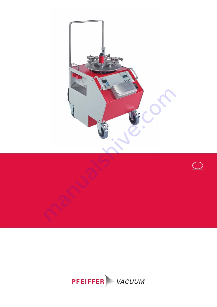
OPERATING INSTRUCTIONS
EN
Translation of the original instructions
CALIBRATION SYSTEM PRO
for calibration of vacuum gauges
Страница 1: ...PA 0409 BEN A 1901 OPERATING INSTRUCTIONS EN Translation of the original instructions CALIBRATION SYSTEM PRO for calibration of vacuum gauges...
Страница 2: ...ation 17 5 Installation 17 5 1 Preparatory work 17 5 2 Connecting accessories 18 5 3 Connecting to the mains power supply 18 6 Operation 19 6 1 Handling of the calibration system 19 6 2 Requirements f...
Страница 3: ...3 11 Technical data and dimensions 33 11 1 General 33 11 2 Technical data 33 11 3 Dimensions 34 12 Appendix 35 12 1 Examples for measurement accuracies 35 Declaration of conformity 37...
Страница 4: ...this document the following hazard levels and information are considered Calibration system BASIC Operating Instructions Operating instructions for vacuum gauges see product descriptions Declaration o...
Страница 5: ...with a reference gauge DAkkS DKD R 6 2 Calibration of measuring equipment for vacuum This directive determines the minimum requirements for the calibration of measuring equipment It does not replace...
Страница 6: ...etc which are not documented in the corresponding product documentations operates the product with accessories which are not documented in the correspond ing product documentations The responsibility...
Страница 7: ...l or operate the calibration system with cleaning agent Do not operate the calibration system with open high vacuum flange Do not carry out any unauthorised modifications or conversions to the pumps T...
Страница 8: ...freely accessible so that you can disconnect it at any time WARNING Danger due to lack of power disconnection device Pump and electronic drive unit are not equipped with a power disconnection device I...
Страница 9: ...does not decrease below the nominal value Obey the operating instructions of the display control unit DCU 110 regarding the speed control of the turbo pump DANGER Danger of excessive pressure in the v...
Страница 10: ...backing pump to 22 hPa NOTICE Risk of overpressure in the calibration system with pressurized gas connection The max permitted pressure at the inlet of the gas dosing valve is 500 hPa relative pressur...
Страница 11: ...of installation kg WARNING Danger from falling parts If you transport the unit by hand parts can fall or slip and can thus cause danger Always transport the unit with 2 persons two handed Wear safety...
Страница 12: ...tood these operating in structions as well as all further applicable documents before starting with the work es pecially the safety instructions maintenance instructions and overhaul instructions Mana...
Страница 13: ...he calibration system only indoors at temperatures of between 10 C to 40 C preferably at room temperature of 20 C In rooms with humid or aggressive atmosphere or during long term storage Store the cal...
Страница 14: ...plate Scope of delivery Calibration system BASIC inclusive Calibration recipient Turbo pump HiCube 80 Rotary vane pump DUO 3 Control unit DCU 110 Calibration set consisting of Display unit TPG 361 Pir...
Страница 15: ...0 7 Valve V2 2 Flange connections for vacuum gauges 8 Valve V1 3 GAV EVN 116 9 Backing pump DUO 3 4 Vacuum chamber figure exemplified 10 Display control unit DCU 110 5 Butterfly valve 11 Display unit...
Страница 16: ...e master switch The display control unit 3 takes over the control and monitoring The backing pump 6 generates the necessary fore vacuum for the turbo pump On top of the vacuum chamber are depending on...
Страница 17: ...cessible at all times No special foundation or base is necessary for installation The unit must not be used outdoors Prerequisites The ambient conditions specified for the area of use Installation loc...
Страница 18: ...operating manuals of the individual components Information about approved accessories see chapter Accessories Use original accessories only NOTICE Note the factory settings The accessory connections...
Страница 19: ...s at ATM and VAC Diaphragm gauges at zero of scale You can easily establish the required pressure conditions for this adjustment with the cal ibration system compared to many process vacuum systems Ca...
Страница 20: ...an lead to non negligi ble measuring uncertainty Vacuum gauges at operating temperature All UUC must be at operating temperature UUC thermally stabilized min 3 hours operating time UUC not thermally s...
Страница 21: ...ections on the vacuum chamber closed Keep blind flanges and protect them agains dirt Extended calibration range You can connect additional reference gauges in order to achieve a higher accuracy or to...
Страница 22: ...on NOTICE Danger of overpressure in the calibration system by pressurized gas connection The max permitted pressure at the inlet of the gas dosing valve is 500 hPa relative pressure Connect a safety v...
Страница 23: ...operation see p 22 chap 6 4 Proceed as follows to do the zero adjustment ZERO and the offset correction Close the GAV to achieve an acceptable base pressure p0 Do the zero adjustment ZERO and the offs...
Страница 24: ...ap 6 2 The calibration system is ready for operation see p 22 chap 6 4 The zero adjustment ZERO and the offset correction have been done see p 23 chap 6 5 Proceed as follows for the dynamic direct com...
Страница 25: ...rfly valve completely Pump down the vacuum chamber to a pressure at least one decade lower than the lowest pressure of the intended calibration range Close the butterfly valve in order to achieve a st...
Страница 26: ...have switched off the calibration system the following starting position has been reached The turbo pump is in standstill 0 Hz The vacuum chamber is vented The bypass line is vented V1 valve between b...
Страница 27: ...3E 05 1 02E 04 2 76 2 00E 04 1 99E 04 2 09E 04 4 99 4 00E 04 4 01E 04 4 23E 04 5 53 7 00E 04 6 99E 04 7 33E 04 4 97 1 00E 03 1 00E 03 1 03E 03 2 52 2 00E 03 2 00E 03 2 03E 03 1 53 4 00E 03 4 00E 03 4...
Страница 28: ...1 00E 04 1 00E 03 1 00E 02 1 00E 01 1 00E 00 1 00E 05 1 00E 04 1 00E 03 1 00E 02 1 00E 01 1 00E 00 1 00E 01 1 00E 02 1 00E 03 Measured pressure hPa Reference gauge pressure hPa Reference gauge vs Mea...
Страница 29: ...For all other cleaning maintenance or repair work contact your Pfeiffer Vacuum ser vice point WARNING Danger to life from electric shock during maintenance and service work The device is completely fr...
Страница 30: ...y arrange maintenance of the pumping components by Pfeiffer Vacuum Service Installation and commissioning in accordance with manual 8 3 Disposal Dispose of substances in accordance with the applicable...
Страница 31: ...he supply lines of the pumping sta tion Check the 24 V output voltage on the DC out terminal of the power supply unit Check the plug contacts on the power supply unit Check the connection cable betwee...
Страница 32: ...0 l s Leave electronic drive on the pump Close the flange openings by using the original protective covers If possible send pump or unit in the original packaging Sending of contaminated pumps or devi...
Страница 33: ...3 hPa 1 1 10 3 100 1 0 1 0 75 kPa 10 0 01 1000 10 1 7 5 Torr mm Hg 1 33 1 33 10 3 133 32 1 33 0 133 1 1 Pa 1 N m2 mbar l s Pa m3 s sccm Torr l s atm cm3 s mbar l s 1 0 1 59 2 0 75 0 987 Pa m3 s 10 1...
Страница 34: ...34 Technical data and dimensions 11 3 Dimensions Fig 2 Dimensions The flange connections are exemplified 503 639 700 1035...
Страница 35: ...ence gauges upper range values 1000 hPa 10 hPa and 0 1 hPa 0 1 1 10 100 1 E 05 1 E 04 1 E 03 1 E 02 1 E 01 1 E 00 1 E 01 1 E 02 1 E 03 Relative deviation Pressure hPa CMR 361 CMR 362 CMR 363 CMR 364 C...
Страница 36: ...36 Appendix...
Страница 37: ...ion system Pro Harmonised standards and national standards and specifications which have been ap plied EN ISO 13857 2008 Safety distances EN ISO 12100 2010 Safety of machinery General principles for d...
Страница 38: ...are the only supplier of vacuum technology that provides a complete product portfolio COMPETENCE IN THEORY AND PRACTICE Benefit from our know how and our portfolio of training opportunities We suppor...