6
VB 230/400-25
6.
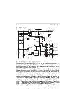
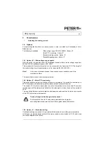
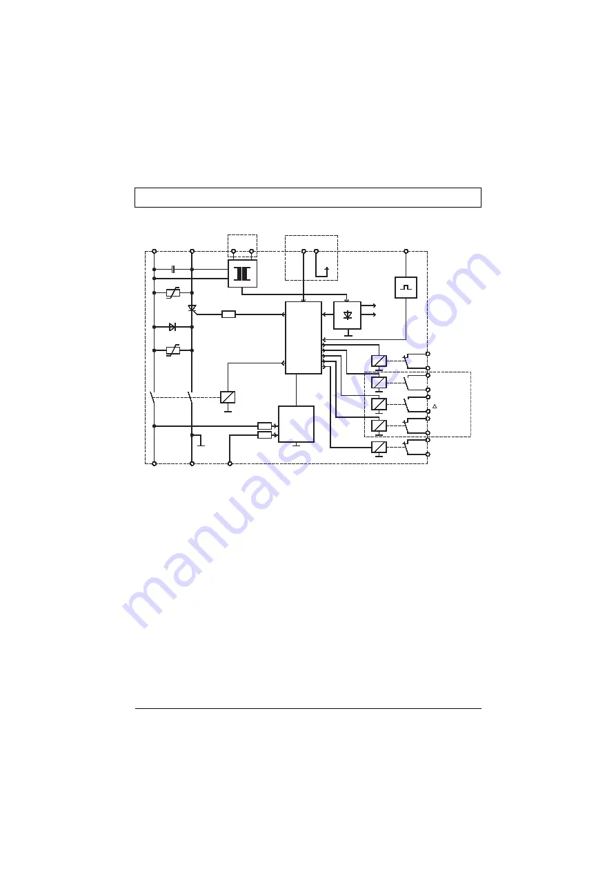
Block diagram
7.
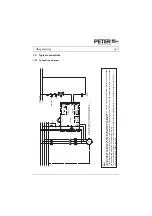
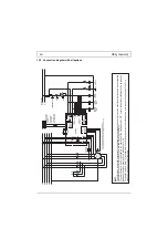
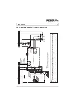
Functional description (see connection diagram)
After switching on the operating voltage on 1L1 and 3L2, the main contactor interlock X5, X6
(lock) and the fault signalling contact X7, X8 (alarm) close. The motor can be started.
A starting logic makes sure that braking is not yet initiated when the plant is switched on with the
master switch while the motor is still switched off.
The fully automatic run of the braking interval starts with the switch-off of the motor contactor
which at the same time closes the contact X3, X4 (start). In the case of very dirty or corroded
control contacts, it may happen that the current of 10mA required for starting cannot flow via the
contacts X3 and X4, as a result of which a braking operation is not started either. In such cases, it
is necessary either to change the control contact or to connect a relay as a link between the
control contact of the motor contactor and the starting contacts X3 and X4. During braking, the
main contactor is interlocked via the contact X5, X6 (lock). After a delay time which, dependent on
the amount of the remanent voltage of the motor, optimizes itself, the braking relay pulls in. Then
an adjustable d.c. voltage is applied to the motor winding. The magnetic field resulting from this
has a braking effect on the still rotating rotor. The d.c. voltage is generated by a thyristor phase
control. Special circuits protect the power semiconductors against overvoltage. With the potentio-
meter "I" the braking torque can be adjusted in wide ranges. Experience shows that a braking
current 2.5 times as high as the rated motor current has a good braking effect.
Adjustments exceeding the rated motor current are indicated by a flashing „ready“-LED.
1L1
3L2
MOTORCONTACTOR
24V
5V
Controller
Braking relay
Remanence
detection
Standstill
detection
2T1
4T2
6T3
Motor contactor
interlocking
Y - Contactor
- Contactor
Standstill
indication
optional
Fault
indication
optional
PTC
X1
X2
optional


