2
0
2
1
-0
5
16
VBA-4E4A-G20-ZEJ/M3L-P9
Installation
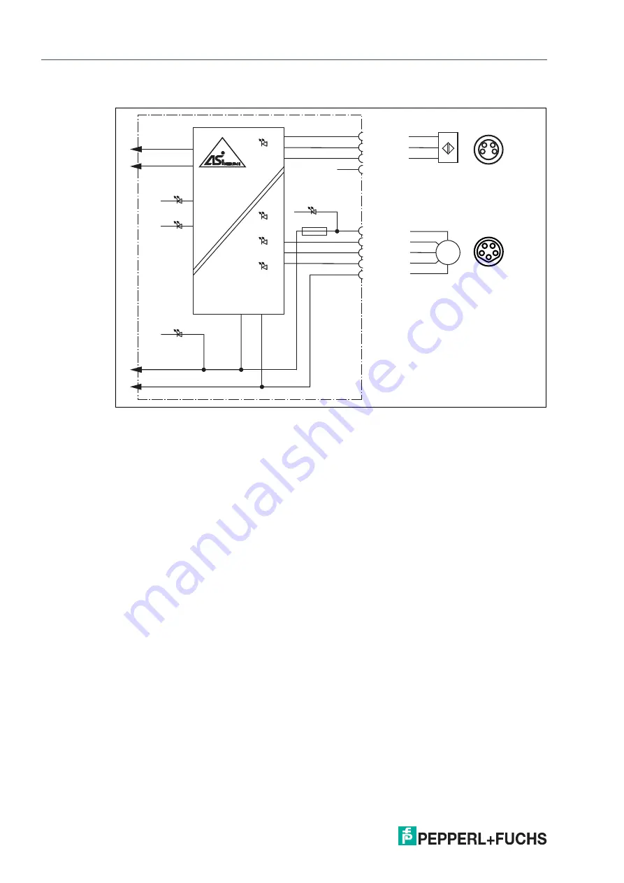
4.4
Connecting motors and sensors
Figure 4.4
Connection wiring diagram for motors and sensors
(n.c.)
PWR
AUX+
AUX-
AS-Int
AS-Interface -
FAULT
AUX
1
4
3
2
IN
1
2
4
5
3
FUSE
IN1 & IN2
IN+
IN
IN-
MOT1 & MOT2
MOT+
DIR
ERROR
SPEED
MOT-
3
1
4
2
M
3
1
4
2
5
DIR
ERR
MOT


