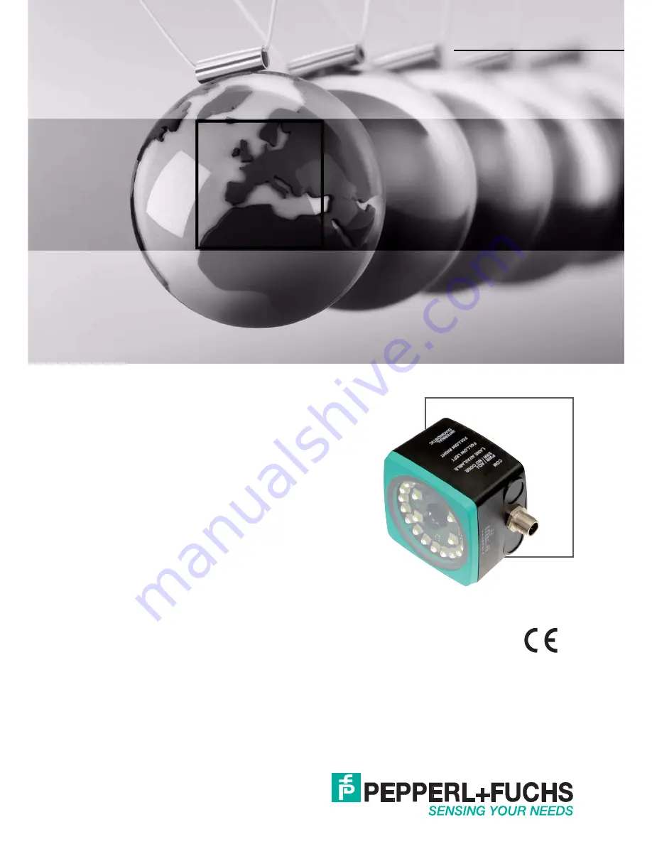
PGV...-F200/-F200A...-R4-V19
Incident Light Positioning System
FACTORY AUTOMATION
MANUAL
Страница 1: ...PGV F200 F200A R4 V19 Incident Light Positioning System MANUAL ...
Страница 2: ...s of Delivery for Products and Services of the Electrical Indus try published by the Central Association of the Electrical Industry Zentralverband Elektrotechnik und Elektroindustrie ZVEI e V in its most recent version as well as the supplementary clause Expanded reservation of proprietorship PGV F200 F200A R4 V19 ...
Страница 3: ...de Tape 14 3 3 Electrical Connection 30 4 Commissioning 32 4 1 Specifying the First Direction Decision 32 4 2 Direction Decision 32 4 3 Parameter assignment 34 4 3 1 Internal Parameterization Using Parameterization Software 34 4 3 2 External Parameterization Using Code Cards 35 5 Operation and communication 37 5 1 Communication via the RS 485 Interface 37 5 1 1 Request Telegram 37 5 1 2 Position R...
Страница 4: ... 1 Code Cards with Special Functions 48 6 1 2 Code Cards for Setting the Read Head Address 51 6 1 3 Code Cards for Adjusting the Resolution 52 6 1 4 Code cards for setting the transfer rate 53 6 1 5 Code cards for adjusting the terminator 55 6 1 6 Code Cards for Adjusting Input Output 3 56 ...
Страница 5: ... of conformity Attestation of conformity Certificates Control drawings Instruction manual Other documents 1 1 2 Manufacturer 1 1 3 Target Group Personnel Responsibility for planning assembly commissioning operation maintenance and dismounting lies with the plant operator Only appropriately trained and qualified personnel may carry out mounting installation commissioning operation maintenance and d...
Страница 6: ...ayed in descending order as follows Informative Symbols Action This symbol indicates a paragraph with instructions You are prompted to perform an action or a sequence of actions Danger This symbol indicates an imminent danger Non observance will result in personal injury or death Warning This symbol indicates a possible fault or danger Non observance may cause personal injury or serious property d...
Страница 7: ...ck to the floor or a painted color lane to track the lane The read head detects Data Matrix tags to navigate within a grid The read head also detects control codes and position markers in the form of Data Matrix codes printed on a self adhesive code tape Data Matrix code tapes and Data Matrix tags have priority over colored tapes or colored lanes The Data Matrix code tapes are installed in a fixed...
Страница 8: ...tag to the controller The tag mode allows the AGV to move freely in as large a grid as desired without having to mark the crossing paths with lane tapes Figure 2 2 Automated guided vehicle with Data Matrix tags The read head switches automatically between tag mode and lane tracking This allows an automated guided vehicle to be guided from one Data Matrix tag grid via a colored or Data Matrix lane ...
Страница 9: ...cordingly The RS 485 interface supports the following transfer rates 38400 bit s 57600 bit s 76800 bit s 115200 bit s preset value 230400 bit s Data structure of the RS 485 interface 2 3 LED Indicators and Controls The read head is equipped with seven indicator LEDs for carrying out visual function checks and rapid diagnostics The read head is equipped with two buttons at the back for activating p...
Страница 10: ... tape detected x x Off x x x Colored tape outside read range x x x Off Off x No direction selection activated43 3 See chapter 4 x x x Lights up Off x Follow left hand lane activated x x x Off Lights up x Follow right hand lane activated x x x Lights up Lights up x Straight ahead activated Flashes x x x x x RS 485 data transfer Flashes Flashes red Flashes Flashes Flashes Off Normal operation Indica...
Страница 11: ... Order designation Description PGV CC25 0 Data Matrix control codes PGV M CA25 Data Matrix position tape PGV CR25 Repair tape PGV85 CT4 Data Matrix tag PGV25M CD100 CLEAR Protective film for code and colored tape PGV33M CB19 BU Colored tape blue PGV33M CB19 GN Colored tape green PGV33M CB19 RD Colored tape red PCV SC12 PCV SC12A Grounding clip V19 G ABG PG9 FE Grounding terminal and plug set PCV U...
Страница 12: ...ected a colored tape this colored tape can move in the Y direction from the zero point within the viewing window The maximum Y value at which the read head can still capture this distance is designated as Y Value Out in the following table If the read head swivels onto a colored tape the read head can capture the distance of the colored tape from the zero point only if the tape is less than a cert...
Страница 13: ...0A R4 V19 Installation 2019 03 13 Read Head Dimensions Figure 3 1 Housing F200 Figure 3 2 Housing F200A 12 5 54 20 20 M12 M12 M6 x 9 4x 25 21 75 25 12 70 13 8 70 80 10 70 12 94 5 70 50 22 ø 25 M6 x 9 4x 12 5 20 20 ...
Страница 14: ... complementary color Due to the integrated lighting of the read head some floor colors appear to be different in the camera If you have problems with the color selection of the colored tapes please consult your contact at Pepperl Fuchs Mounting the Colored Tape 1 Clean the surface of any greasy or oily deposits and dust 2 Ensure that the surface is dry clean and stable 3 Please observe the followi...
Страница 15: ...18 mm The zero point is located in the center of the colored tape You can use 3 defined colors See the section entitled Colored tape The sensor always moves in the X direction In the sensor s field of view X indicates an upward movement Figure 3 3 Field of view and coordinates of the sensor Figure 3 4 Curve radius R 50 cm Select a curve radius that can handle the turning circle of your automated g...
Страница 16: ...rection information The output angle covers the range from 45 to 45 The resolution is 1 Figure 3 5 Relative angle Data Matrix code tape The read head detects the absolute angle in relation to the tracked lane with a maximum resolution of 0 1 The angle is specified absolutely relative to the tracked lane since a Data Matrix code contains tape direction information The output angle covers the range ...
Страница 17: ...ored tape or a Data Matrix code tape and outputs this value to the controller The output value is different for colored tapes and Data Matrix code tapes due to the lack of an X position for colored tapes Colored tape The read head outputs the Y value at which the colored tape intersects the Y axis as the distance Figure 3 7 Distance A for colored tape X Y α X Y α X Y A ...
Страница 18: ...GV F200 F200A R4 V19 Installation Data Matrix code tape The read head indicates the vertical distance of the zero point in relation to the Data Matrix code tape Figure 3 8 Distance A for Data Matrix code tape X Y A ...
Страница 19: ...ranches Follow left hand lane Straight ahead Follow right hand lane The direction decision is signaled to the read head via the controller If there is no direction decision the read head displays an error message Code Tapes for Control and Positioning In addition to tracking the lane the read head can also detect Data Matrix codes This process involves evaluating both control and position informat...
Страница 20: ...A R4 V19 Installation Branches or intersections with position information can be displayed as follows Figure 3 10 Separate lane branches off converges Colored tape Data Matrix position code Data Matrix control code 1 3 2 1 2 3 ...
Страница 21: ...of view colored tapes or colored lanes in the field of view are ignored Note Branches Intersections with Data Matrix Position Code Observe the following guidelines less than 1 m before and after branching or intersection of a lane with a position code The position codes of the main lane must run continuously for 2 m The position codes of the branching intersecting lane must run continuously for 1 ...
Страница 22: ... the straight lane if the direction decision follow right hand lane has been made A second lane branches off to the right from the straight lane The read head follows the straight lane if the direction decision follow left hand lane has been made A single lane with a position code turns to the left or right The read head follows the position code if the direction decision straight ahead has been m...
Страница 23: ...es at branches or intersections Figure 3 13 Mixture of lanes with colored tape and Data Matrix codes Control codes can be mounted in the immediate vicinity of a branch with Data Matrix codes for positioning but not near an intersection The control code must be mounted directly next to the guiding lane Figure 3 14 Branch with control code ...
Страница 24: ...s must be observed when creating the lanes Offset V between position codes of a lane must not be greater than 5 mm Figure 3 15 Offset 0 mm V 5 mm The distance D between the colored tapes at a branch or intersection as a separate lane must not exceed 15 mm The distance decreases if the guiding colored tape cannot be detected by the read head in the center of the reading window V ...
Страница 25: ...19 Installation 2019 03 25 Figure 3 16 Distance 7 5 mm D 15 mm The distance between the Data Matrix code tapes at a branch or intersection as a separate lane must be between 0 mm and 5 mm Figure 3 17 Distance 0 mm D 5 mm ...
Страница 26: ...nce between a Data Matrix position code and a Data Matrix control code must be between 0 mm and 5 mm Figure 3 19 0 mm D 5 mm A lane can switch from a colored tape to a Data Matrix code tape and back again as often as required The distance between the colored tape and the edge of the Data Matrix code must be between 0 mm and 10 mm 25 mm D D 25 mm 10 40 mm 25 mm D D 25 mm 25 mm ...
Страница 27: ...eed as follows Installing the Code Tape 1 Clean the surface of any greasy or oily deposits and dust 2 Ensure that the surface is dry clean and stable 3 Pull away a few centimeters of the protective film at the beginning of the code tape Place the code tape at the precise point of the required starting position on the surface and press to attach 4 Then affix the code tape along the desired travel p...
Страница 28: ... Position of 0 m Data Matrix control codes Code Tape Dimensions Order designation Description PGV10M CA25 0 Code tape length 10 m PGV100M CA25 0 Code tape length 100 m Table 3 1 See also data sheet PGV CA25 at www pepperl fuchs com Order designation Description PGV CC25 001 Code tape Control Code 001 length 1 m PGV CC25 999 Code tape Control Code 999 length 1 m Caution Stop edges If you attach ano...
Страница 29: ... A cross in the center of the Data Matrix tag marks the zero point The X and the Y axes are marked starting from the zero point The black arrow indicates the positive axis and the white arrow indicates the negative axis Figure 3 22 Data Matrix tag with the number 99999999 and position information Bend to the left Bend to the right 1 2 5 85 85 ...
Страница 30: ...3 24 Color assignment Pepperl Fuchs female cordsets are manufactured in accordance with EN60947 5 2 When using a type V19 female cordset with an open cable end on the Main connection the colors are assigned as follows Connector Assignment Connection pin Strand color Color abbreviation 1 White WH 2 Brown BN 3 Green GN 4 Yellow YE 5 Gray GY 6 Pink PK 7 Blue BU 8 Red RD 1 2 3 4 5 6 7 8 INPUT_SELECTIO...
Страница 31: ... bonding cable is not laid or cannot be laid A film shield is used The following points relating to shielding must also be noted Use metal cable clips that cover large areas of the shield After installing the cable shield in the control cabinet place it directly on the equipotential bonding rail Direct the protective grounding connections to a common point in a star configuration The cross section...
Страница 32: ...hapter 5 1 4 2 Direction Decision The read head has several ways of following colored tapes and Data Matrix code tapes depending on the parameterization Depending on the input signal the read head follows the right hand the left hand or the better lane Direction Decision via Input Signal t 1 0 1 0 INPUT_SELECTION_DIR_RIGHT INPUT_SELECTION_DIR_LEFT Direction decision 20 ms Error 5 Left Error 5 Left...
Страница 33: ...r color lane Worse color lane Following Lane with More Detailed Position Information You can parameterize the read head so that it follows the Data Matrix code tape that continues the current location information Figure 4 3 More detailed position information New position Information Example Example 1 1 2 2 1 2 108 110 112 114 116 398 400 118 402 404 406 4 0 8 120 122 1 2 4 1 2 1 2 ...
Страница 34: ...ware is available as a free download from www pepperl fuchs com Follow the instructions that appear on your screen during the installation If your PC does not have a built in RS 485 interface you will need a USB RS 485 interface converter Parameterizing the Reader 1 Connect the reader to your PC via the interface converter Information on how to do this can be found in the manual for the interface ...
Страница 35: ... trigger final activation If the ENABLE activation code is detected the green LED2 lights up for 1 second If the activation code is not detected LED2 lights up red for 2 seconds Completing Parameterization Place the parameterization code in the field of vision of the camera module After the parameterization code is detected the green LED2 lights up for 1 second In the event of an invalid parameter...
Страница 36: ...es with the parameters that have just been modified The parameterization is not saved however After being switched off and on again the reading head operates with the last valid parameters that were saved DEFAULT All parameters in the reading head are overwritten with the original default settings Re enter the configuration mode and save the default settings nonvolatile with the code card STORE No...
Страница 37: ...e 8 data bits of the first byte inverted Structure of a Request Telegram Meaning of Bits Byte bit Bit 8 Bit 7 Bit 6 Bit 5 Bit 4 Bit 3 Bit 2 Bit 1 Bit 0 Function Byte 1 Parity 11 1 R W 0 response 1 request Req bit 4 Req bit 3 Req bit 2 Req bit 1 Req bit 0 A1 A0 Request Byte 2 Parity 0 Req bit 4 Req bit 3 Req bit 2 Req bit 1 Req bit 0 A1 A0 Checksum PAR R W Req bit 4 Req bit 3 Req bit 2 Req bit 1 Re...
Страница 38: ...ved Reserved Reserved Reserved Reserved Reserved Byte 10 Parity 0 Reserved Reserved Reserved Reserved Reserved Reserved Reserved Byte 11 Parity 0 ANG13 ANG12 ANG11 ANG10 ANG09 ANG08 ANG07 Byte 12 Parity 0 ANG06 ANG05 ANG04 ANG03 ANG02 ANG01 ANG00 Byte 13 Parity 0 Reserved Reserved Reserved Reserved Reserved Reserved Reserved Byte 14 Parity 0 Reserved Reserved Reserved Reserved Reserved Reserved Re...
Страница 39: ...y 0 ANG13 ANG12 ANG11 ANG10 ANG09 ANG08 ANG07 Byte 12 Parity 0 ANG06 ANG05 ANG04 ANG03 ANG02 ANG01 ANG00 Byte 13 Parity 0 Reserved Reserved Reserved Reserved Reserved Reserved Reserved Byte 14 Parity 0 Reserved Reserved Reserved Reserved Reserved Reserved Reserved Byte 15 Parity 0 TAG_27 TAG_26 TAG_25 TAG_24 TAG_23 TAG_22 TAG_21 Byte 16 Parity 0 TAG_20 TAG_19 TAG_18 TAG_17 TAG_16 TAG_15 TAG_14 Byt...
Страница 40: ... No absolute X position O1_ O2_ Orientation control code for lane Refer to section Orientation O RP Repair tape detected S1_ S2_ Relative position control code for lane Refer to section Side S TAG Data Matrix tag detected TAG_ Data Matrix tag with number detected WRN Warning message Warnings are stored in WRN00 WRN13 Additional information on the codes can be found in the Warning Messages table XP...
Страница 41: ...elation to the code tape WRN06 Low level of code contrast WRN07 Repair tape detected WRN08 Temperature too high WRN09 Position code near branch crossover detected WRN10 More than the specified number of code lanes present WRN11 Reserved WRN12 Reserved WRN13 Reserved Table 5 5 If no warnings are present the bits are set to 0 Note 16 bit 32 bit In order for the response telegrams from the read head ...
Страница 42: ...anes found 1 1 3 or more lanes found O1 O0 Meaning 0 0 Control code has the same orientation as ascending Data Matrix lane 0 1 Orientation of control code rotated 90 clockwise in relation to ascending Data Matrix lane 1 0 Orientation of control code rotated 180 clockwise in relation to ascending Data Matrix lane 1 1 Orientation of control code rotated 270 clockwise in relation to ascending Data Ma...
Страница 43: ...ition XP and the Y position and angle YPS ANG Meaning of Bits S1 S0 Meaning 0 0 No control code is present or found Reserved 0 1 Control code to the right of the Data Matrix or color lane 1 0 Control code to the left of the Data Matrix or color lane 1 1 Not detectable1 1 Control code laid on Data Matrix lane No Data Matrix lane Example TAG NL NP XP YPS ANG Meaning 0 0 0 1 1 Valid data present Colo...
Страница 44: ...B1 2 B2 2 XOR B1 1 B2 1 XOR B1 0 B2 0 LL RL Meaning 0 0 Error code 5 0 1 Follow right hand lane 1 0 Follow left hand lane 1 1 Straight ahead Table 5 6 See chapter 4 2 Example Request telegram when read head address 0 Request Response Description Example 0xE8 0x17 See Response Telegram for Direction Decision Follow left hand lane 0x02 0xE4 0x1B Follow right hand lane 0x01 0xEC 0x13 Straight ahead 0...
Страница 45: ...cksum Note You can only ever request one color Byte bit Bit 8 Bit 7 Bit 6 Bit 5 Bit 4 Bit 3 Bit 2 Bit 1 Bit 0 Byte 1 Parity 0 0 A1 A0 0 R G B Byte 2 Parity 0 0 A1 A0 0 R G B R G B Meaning 0 0 1 Choice of color blue 0 1 0 Choice of color green 1 0 0 Choice of color red Example Request telegram when read head address 0 Request Response Description 0xC4 0x3B 0x01 0x01 Choice of color blue 0x88 0x77 0...
Страница 46: ...made to the layout of a system the relevant control code is simply moved to the new position without requiring program modifications to be made Control codes are short code tapes one meter in length The control code has an encrypted number Control codes exist with numbers ranging from 001 to 999 When the read head enters the range of a control code it sets the control code flag in its output data ...
Страница 47: ...ode tape as accurately as possible Note The repair tape works incrementally In so doing it adds one value to the previous read position on the code tape If the read head starts on a repair tape the read head reports an error Move the read head to a position on the code tape away from the repair tape to read the absolute value Tip If repairs are required the Code Tape Generator at www pepperl fuchs...
Страница 48: ...unctions ENABLE STORE CANCEL USE DEFAULT Figure 6 1 The code card ENABLE is used to activate external parameterization operating mode Note When performing external parameterization with code cards we recommend copying and printing out the relevant pages in this manual and cutting out the code cards This prevents the read head from mistakenly detecting another code card on the same page If you inte...
Страница 49: ...le memory of the read head and terminates external parameterization operating mode Figure 6 3 The CANCEL code card discards the modified parameterization and terminates external parameterization operating mode The read head switches to normal mode and adopts the last valid configuration that was saved Store Cancel Store Cancel ...
Страница 50: ...d head then operates with this configuration However if the read head is switched off and on again the configuration is lost and the read head operates with the last valid configuration that was saved This function is used primarily for test purposes Figure 6 5 The DEFAULT code card restores the settings of the read head to default and terminates external parameterization operating mode Use Defaul...
Страница 51: ... that it can be activated via the interface The address range extends from 0 3 Figure 6 6 The code card assigns address 0 to the read head Figure 6 7 The code card assigns address 1 to the read head Figure 6 8 The code card assigns address 2 to the read head Read Head Address 0 Read Head Address 1 Read Head Address 2 Adresse 0 Adresse 1 Adresse 2 ...
Страница 52: ...ion enables you to assign a position data resolution of 0 1 mm 1 mm 10 mm to the read head Figure 6 10 The code card assigns a position data resolution of 0 1 mm to the read head Figure 6 11 The code card assigns a position data resolution of 1 mm to the read head Read Head Address 3 Adresse 3 Resolution 0 1 mm Resolution 1 mm Resolution 0 1 mm Resolution 1 mm ...
Страница 53: ...various transfer rates to the reading head for communication via the interface The following transfer rates are available 38400 bit s 57600 bit s 76800 bit s 115200 bit s 230400 bit s Figure 6 13 The transfer rate of the read head for communication via the interface is preset to 38400 bit s Resolution 10 mm Resolution of the read head mm Maximum length of the code tape km 10 10 1 10 0 1 10 Resolut...
Страница 54: ...600 bit s Figure 6 15 The transfer rate of the read head for communication via the interface is preset to 76800 bit s Figure 6 16 The transfer rate of the read head for communication via the interface is preset to 115200 bit s Transfer rate 57600 bit s Transfer rate 76800 bit s Transfer rate 115200 bit s 57600 Bit s 76800 Bit s 115200 Bit s ...
Страница 55: ...preset to 230400 bit s 6 1 5 Code cards for adjusting the terminator Parameterization enables you to switch a terminator on and off in the read head Figure 6 18 The terminator is deactivated Figure 6 19 The terminator is connected Transfer rate 230400 bit s 230400 Bit s Terminator OFF Terminator ON Termination off Termination on ...
Страница 56: ...utput functions are available Input none Output Overspeed Output Warning Output Fault Output Event Output No position Figure 6 20 Input output 3 is defined as an input but has no function Figure 6 21 Input output 3 is defined as an output This output carries the potential UB as long as the defined maximum speed is exceeded Input 3 No Function Output 3 Overspeed Input 3 No function Output 3 Overspe...
Страница 57: ...e 6 23 Input output 3 is defined as an output This output carries the potential UB as long as an error message is present on the read head Figure 6 24 Input output 3 is defined as an output This output carries the potential UB as long as an event marker is present in the read field of the read head Output 3 Warning Output 3 Fault Output 3 Event Output 3 Warning Output 3 Error Output 3 Event ...
Страница 58: ...00 F200A R4 V19 Appendix Figure 6 25 Input output 3 is defined as an output This output carries the potential UB as long as the read head is not reading any position information Output 3 No position Output 3 No position ...
Страница 59: ...chs GmbH 68307 Mannheim Germany Tel 49 621 776 0 E mail info de pepperl fuchs com USA Headquarters Pepperl Fuchs Inc Twinsburg Ohio 44087 USA Tel 1 330 4253555 E mail sales us pepperl fuchs com Asia Pacific Headquarters Pepperl Fuchs Pte Ltd Company Registration No 199003130E Singapore 139942 Tel 65 67799091 E mail sales sg pepperl fuchs com DOCT 3707D 03 2019 ...