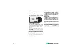
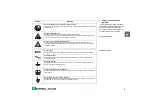
Pepperl+Fuchs LUC-T Series Скачать руководство пользователя страница 42

4

1

Notes on safety

The compact transmitters LUC-T have been designed to operate safely in accordance with current 
technical and safety standards and must be installed by qualified personnel according to the 
instructions in this manual. The manufacturer accepts no responsibility for any damage arising from 
incorrect use, installation or operation of the equipment. Changes or modifications to the equipment 
not expressly approved in the operating instructions or by the bodies responsible for compliance may 
make the user’s authority to use the equipment null and void. Damaged instruments which may be a 
safety hazard must not be operated and are to be marked as defective.

Use in hazardous areas
When used in explosion hazardous areas, the equipment must be installed in accordance with local 
regulations as well as with the technical and safety requirements on the measuring point as specified 
in the accompanying certificates.

Installation and commissioning
Installation, electrical connection, commissioning, operation and maintenance may only be carried out 
by trained and authorized personnel. The personnel must read and understand these operating 
instructions before carrying them out.

Operation
The instruments may only be operated by trained personnel authorized by the plant operator. The 
instructions given in this manual are to be followed exactly.
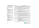
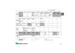
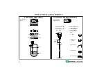
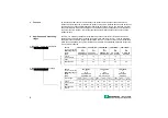
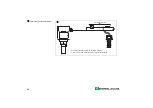
LUC-T

!!

-

!!!

-

!!!

-

!!

LUC-T10
2-wire Ex

LUC-T20

2-wire and 4-

wire non Ex

LUC-T30

4-wire

Dust-Ex

NA

x

x

EX

EEx ia IIC, Zone1 / Atex II 2 G

x

FM

FM, Class I, Division 1, Groups A-G 

1)


x

F1

FM, Class II, Division 1, Groups E-G

x

CS

CSA, Class I, Division 1, Groups A-G 

1)


x

C1

CSA, Class II, Division 1, Groups E-G

x

CG

CSA General Purpose

x

x

SX

BVS/DMT (ST-Ex) Zone 10 / ATEX II 1/3 
D

x

T1

TIIS Ex ia II C T6

x

1) for version 

LUC-T

!!

-N5

!

-

!!!

-

!!

 and 

LUC-T

!!

-N6

!

-

!!!

-

!!

 only

Содержание LUC-T Series

Страница 1: ...d e f KA 042O 98 a3 07 01 Software 2 2 52010959 LUC T10 LUC T20 LUC T30 F llstandmessung mit Ultraschall Ultrasonic level measurement Mesure de niveau ultrasonique d e f...

Страница 2: ...vom Zentralverband Elektrotechnik und Elektroindustrie ZVEI e V in ihrer neuesten Fassung sowie die Erg nzungsklausel Erweiterter Eigentumsvorbehalt Wir von Pepperl Fuchs f hlen uns verpflichtet eine...

Страница 3: ...d KA 042O 98 de 07 01 Software 2 2 52010959 LUC T10 LUC T20 LUC T30 F llstandmessung mit Ultraschall d...

Страница 4: ...lay mehr Funktionen mit gestecktem Display 1 Reset Ger t V9H5 Eingabe 2 L ngeneinheit V8H2 Eingabe m ft 333 0 1 3 Abgleich Leer V0H1 Eingabe 4 Abgleich Voll V0H2 Eingabe 5 Anwendung V0H3 Eingabe E m f...

Страница 5: ...ck ber die Bedienm glichkeiten 16 10 Tastenbedienung ohne Display ohne Matrix 16 11 Bedienung ohne Matrix 17 12 Bedienung ber Matrix 18 12 1 Tastenbedienung vor Ort mit gestecktem Display 18 12 2 Bedi...

Страница 6: ...ischen und sicherheitstechni schen Auflagen an die Messstelle einzuhalten Montage und Inbetriebnahme Montage elektrischer Anschluss Inbetriebnahme und Wartung der Messeinrichtung darf nur durch ausgeb...

Страница 7: ...fiziert sein wenn nur Anschlussleitungen in den explosionsgef hrdeten Bereich f hren Gleichstrom Eine Klemme an der Gleichspannung anliegt oder durch die Gleichstrom flie t Wechselstrom Eine Klemme an...

Страница 8: ...LUC T Reihe umfasst drei Sensoren mit verschiede nen Elektronikvarianten und abgestuften Messbereichen ab 0 25 m 2 Draht 4 mA 20 mA Loop powered LUC T 4 Draht separate Spannungsversorgung LUC T Sensor...

Страница 9: ...er speiseger t z B SPS bei LUC T10 Anschluss ber Ex Tren ner Z Barriere Bedienung ber Handbedienger t Protokoll HART z B KFD2 STC3 Ex1 Anschluss von bis zu 10 Transmit tern an PROFIBUS PA Bedienung be...

Страница 10: ...hren Montieren Sie niemals zwei LUC T in einem Beh lter da sich die Ger te in ihrer Funktion beeintr chtigen k nnen Montieren Sie den Sensor nicht in der Mitte der Beh lterdecke Installieren Sie den S...

Страница 11: ...Die empfohlenen Abmessungen des Stutzens sind Richtwerte in deren Grenzen Sie den Stutzen variieren k nnen W hlen Sie den Stutzen durchmesser gro genug aber hal ten Sie die Stutzenh he immer so klein...

Страница 12: ...toff 1 4301 Montage mit Adapter flansch zylindrisches Gewinde LUC Z Ausf hrung F73 DN 50 PN 16 F93 DN 80 PN 16 FA3 DN 100 PN 16 Gewinde G5 G1 ISO 228 G6 G2 ISO 228 Material S 1 4435 P PPs Polypropylen...

Страница 13: ...hmesser 5 mm 9 mm M8 215 158 11 119 2 25 120 123 25 Montage mit Montageb gel Bestell Nr LUC Z12 Werkstoff 1 4301 2 x M8 x 12 und 2 x Federring beiliegend Zone 10 berwurfflansch Stutzen Zone 10 Sensor...

Страница 14: ...Abschirmung Bei Verwendung von nicht abgeschirmtem Kabel kann das digitale Kommunikationssignal unter Umst nden beeintr chtigt werden LUC T10 LUC T20 2 Draht Loop powered LUC T20 Vierdraht inklusive...

Страница 15: ...d Bedienung PROFIBUS PA siehe BA 166O LUC T mit PROFIBUS PA on address off L 4 L 5 V V H H on adress off PROFIBUS PA 1 2 3 4 5 6 7 8 2 8 10 1 2 3 4 5 6 7 8 LUC T10 LUC T20 LUC T30 PROFIBUS PA 9 V 32 V...

Страница 16: ...14 Anschluss der Handbedienger te R I O Gesamtwiderstand 250 W Anschluss des Handbedienger tes berall entlang der 4 mA 20 mA Leitung oder direkt am LUC T...

Страница 17: ...LUC T eine St rung leuchtet die rote LED blinkt der Bargraph bei gestecktem Display nimmt der Stromausgang den ge w hlten Wert ein 10 2 4 mA 110 HOLD wird ein Fehlercode in V9H0 ausge geben Erkennt d...

Страница 18: ...g ohne Matrix ohne Display Bedienung mit PACTware am PC etc siehe Doku mentation zur PACTware Tastenbedie nung vor Ort mit gesteck tem Display Seite 18 Bedienung ber Hand bedienger t ohne Display Seit...

Страница 19: ...lter bis zum Punkt Leer f llen gleichzeitig und dr cken Vollabgleich 100 Beh lter bis zum Punkt Voll f llen gleichzeitig V und H dr cken Verriegeln Schutz aller Eingaben gegen ungewollte und unbefugte...

Страница 20: ...2 V1 V0 V2 V3 V4 H0 H1 H2 H3 H4 Tasten Funktion Anwahl des Matrixfeldes Anwahl der vertikalen Matrixposition Anwahl der horizontalen Matrixposition R cksprung auf V0H0 Eingabe der Parameter Aktiviert...

Страница 21: ...ie Parameter werden ber Unter menues eingestellt I O LUC T Online 1 Group Select 2 PV 8 7 m HELP F1 F4 F2 F3 LUC T LIC0001 Online 1 Group Select 2 PV 8 7m HELP F1 F4 F2 F3 LUC T LIC0001 Group Select 1...

Страница 22: ...indrisch liegender Tank Stromausgang einstellen 24 analog digital Echoqualit t Verz gerungs zeit St recho ausblendung Erstechofaktor Simulation Messwerte Angaben zur Messstelle Matrixfeld Anzeige Matr...

Страница 23: ...F llh he in V0H8 Distanz in m ft V0H9 F llh he in m ft Achtung Alle nachfolgenden Eingaben Lineari sierung Stromausgang Festzielaus blendung m ssen in der Einheit des Abgleichs erfolgen BD E F VH Ein...

Страница 24: ...sierungs kurve geht der Stromausgang auf St rung und das Ger t misst nicht weiter Folgende Fehler meldungen k nnen erscheinen E605 Anzeige w hrend der Eingabe der Li nearisierungskurve Die Fehlermeldu...

Страница 25: ...xt 1 V2H0 4 H L schen 2 V2H0 3 H Auslitern 3 V2H1 7 H Zeilen Nr 4 V2H2 z B 4 000 m H F llstand 5 V2H3 z B 5000 l H Volumeneingabe 6 V2H1 6 H Zeilen Nr nach Eingabe aller Wertepaare V2H0 1 H Tab aktivi...

Страница 26: ...20 Der Stromausgang befindet sich au er halb des eingestellten Bereichs kleiner 3 8 mA gr er 20 5 mA berpr fen Sie den Abgleich und die Einstellungen des Stromaus gangs 2 M glichkeiten Stromausgang li...

Страница 27: ...kannt kann ein anderer Einbauort gew hlt oder das St recho ausgeblendet werden St rechoausblendung Die St rechoausblendung wird angewandt wenn nicht der tats chliche F llstand sondern eventuelle Einba...

Страница 28: ...60 s w hlbar 0 s 255 s Ist F llh he Verf lschungen der F llh he in V0H9 z B durch Temperatureinfluss k nnen durch Ein gabe der tats chlichen F llh he Ist F llh he in V3H1 korrigiert werden Die Eingabe...

Страница 29: ...e Tastatur siehe Hinweis Verriegeln ber Tastatur VH Eingabe Text 1 V9H6 1 H Simulation H he 2 V9H7 z B 2 000 H Simulierte H he z B 2 m 3 V9H8 V0H0 Anzeige Strom erscheint auch am Bargraph Anzeige H he...

Страница 30: ...ehler Pepperl Fuchs Service Line anrufen E 116 St rung Fehler beim Download Reset durchf hren oder neuen Download mit kor rigierten Daten starten E 125 St rung Sensor defekt Sensoranschluss berpr fen...

Страница 31: ...e Line anrufen Sensorposition berpr fen siehe Seiten 8 11 25 Linearisierungskurve neu einge ben siehe Seiten 22 23 Werte in V0H5 und V0H6 berpr fen und eventuell neu eingeben siehe Seite 24 Messwert i...

Страница 32: ...ationszeit erh hen siehe Seite 24 bei R hrfl geln im Messbereich Sensorposition berpr fen siehe Seiten 8 11 25 Anwendungsparameter 0 oder 2 in V0H3 w hlen siehe Seite 21 Bei konstantem F ll stand spri...

Страница 33: ...e F llh he m ft Linearisierungs tabelle Volumen Kundeneinheit Volumen endwert Default 100 0 Kundeneinheit Erweiter ter Ab gleich V3 St recho ausblendung Default 0 000 Ist F llh he Default 0 000 Echoqu...

Страница 34: ...Select 2 H1 4 H3 3 H2 5 H4 6 H5 7 H6 8 H7 9 H8 10 H9 2 V2 3 V3 4 V8 Lineari zation Extended parameter Operating parameter Last diagnostic code Type of sensor electronics Instrument software No Rackbu...

Страница 35: ...8 T2 30 Db Schutzart IP67 bei ge ffnetem Geh usedeckel IP20 Schwingungsfestigkeit DIN IEC 68T2 6 Tab 2 C 10 Hz 55 Hz Elektromagnetische Vertr glichkeit St raussendung nach EN 61326 Betriebsmittel der...

Страница 36: ...200 mV max Rauschen gemessen an 500 500 Hz 10 kHz Ueff 2 2 mV Galvanische Trennung Bei allen Vierdraht Varianten ist die Auswerteelektronik von den Versorgungsklemmen galva nisch getrennt Software Ve...

Страница 37: ...ART 32 Matrix LUC T 31 Messbereiche 6 Messbereichsspreizung 24 Me distanz 20 25 Messeinrichtung 7 Me wertabfrage 20 Montage im Rohrstutzen 9 Montage mit Adapterflansch 10 Montage mit Einschwei muffe 9...

Страница 38: ...36...

Страница 39: ...e KA 042O 98 en 07 01 Software 2 2 52010959 LUC T10 LUC T20 LUC T30 Ultrasonic level measurement e...

Страница 40: ...play 3 Empty calibration V0H1 Input 4 Full calibration V0H2 Input 5 Applications V0H3 Input E m ft F m ft 4 Conveyor belt 3 Bulk solids 2 Dome cover 1 Rapid level change Reset Full calibration F Empty...

Страница 41: ...ting procedures 16 10 Key operation without display without matrix 16 11 Operation without matrix 17 12 Operating via the matrix 18 12 1 Local pushbutton operation with plug in display 18 12 2 Operati...

Страница 42: ...th local regulations as well as with the technical and safety requirements on the measuring point as specified in the accompanying certificates Installation and commissioning Installation electrical c...

Страница 43: ...ate if necessary non explosion hazardous areas Devices located in safe areas still require a certificate if their outputs run into explosion hazardous areas Direct voltage A terminal to which or from...

Страница 44: ...be equipped with one of several electronic modules with graduated measuring ranges from 0 25 m 0 82 ft upwards 2 Wire 4 mA 20 mA Loop Powered LUC T 4 Wire including mains power supply LUC T Sensor Pro...

Страница 45: ...the Ex isolator Zener barrier operation via handheld terminal protocol HART e g KFD2 STC3 Ex1 connection to PROFIBUS PA bus for up to 10 transmitters operated by a PC HART Modem Interface to a PC for...

Страница 46: ...y not function correctly Do not mount the sensor in the centre of the vessel roof Install the transmitter at right angles to the surface of the material Do not measure through the filling curtain 6 2...

Страница 47: ...e The recommend nozzle dimensions are limits within which the nozzle can vary Select as big a nozzle diameter as possible but keep the height as small as possible The inner surface of the nozzle shoul...

Страница 48: ...1 AISI 304 Mounting with adapter flange parallel thread LUC Z Process connection F73 DN 50 PN 16 F93 DN 80 PN 16 FA3 DN 100 PN 16 Sensor connection G5 G 1 ISO 228 G6 G 2 ISO 228 Material S 1 4435 AISI...

Страница 49: ...5 8 4 158 6 2 11 0 4 119 4 6 2 0 08 25 120 4 7 123 4 8 25 0 9 0 9 Mounting with mounting bracket Order No LUC Z12 Material 1 4301 AISI 304 2 x M8 x 12 and 2 x springs supplied Zone 10 slip on flange n...

Страница 50: ...ounded in the controlroom or the nearest earthing point A good connection to ground is essential to good screening Under certain circumstances the digital communication signal may be affected if unscr...

Страница 51: ...rument has a unique address off Hardware address on Software address LUC T10 LUC T20 LUC T30 2 wire communication PROFIBUS PA Current consumption LUC T10 LUC T20 12 mA 1 mA LUC T30 16 mA 1 mA Connecti...

Страница 52: ...14 Connecting the handheld terminal R I O total resistance 250 W Connecting the handheld terminal anywhere along the 4 mA 20 mA cable or directly on the compact echo transmitter...

Страница 53: ...LUC T identifies an alarm the bargraph flashes if the display is plugged the red LED lights up the current output adopts a preselected value 10 2 4 mA 110 HOLD an error code is output in V9H0 If the L...

Страница 54: ...guration against a flat wall The level is detected over the distance between LUC T and the wall Operating procedures Operating without matrix without Display Operating with matrix Operating without di...

Страница 55: ...ation 0 fill tank to empty point simultaneously press and Full calibration 100 fill tank to full point simultaneously press V and H Locking Protects the entries against unwanted and unauthorized chang...

Страница 56: ...ontal matrix position The display jumps to V0H0 Entering parameters Activates the appropriate matrix position The selected position flashes Changes the value of the flashing position by 1 Changes the...

Страница 57: ...Parameters are set using submenus I O LUC T Online 1 Group Select 2 PV 8 7 m HELP F1 F4 F2 F3 LUC T LIC0001 Online 1 Group Select 2 PV 8 7m HELP F1 F4 F2 F3 LUC T LIC0001 Group Select 1 Calibration 2...

Страница 58: ...current input 24 Continuous Switch Echo quality Delay time Fixed target suppression First echo Simulation factor Measured values Information on the measuring point Matrix field Display Matrix field D...

Страница 59: ...ers feet V0H9 Level in meters feet Caution All entries which follow linearization current output fixed target suppression must be in the same units as those of the calibration BD E F VH Entry Text 1 V...

Страница 60: ...error and the instrument stops measuring E605 Display when entering the linearization curve The error message disappears when the linearization curve is activated E602 The linearization curve rise no...

Страница 61: ...H Line No 4 V2H2 e g 4 000 m 13 1 ft H Level 5 V2H3 e g 5000 l 1320 USgal H Volume input 6 V2H1 6 H Line No After entering all pairs of values V2H0 1 H Activate table 3 4 5 2 1 6 7 4 m Full e g 5000 l...

Страница 62: ...The current output is outsidethe set range smaller than 3 8 mA greater 20 5 mA Check the calibration and settings of the current output 2 Types of measurement Continuous current output The current fr...

Страница 63: ...function Fixed target echo suppression The fixed target suppression function is used when the level echo is not detected because a fitting is generating a stronger interference echo Up to three inter...

Страница 64: ...s Selectable 0 s 255 s Actual height Falsifications in height in V0H9 e g by temperature effects can be corrected by entering the correct height the actual height in V3H1 Entering the actual height t...

Страница 65: ...6 1 H Simulation height 2 V9H7 e g 2 000 6 600 ft H Simulated height e g 2 m 6 6 ft 3 V9H8 V0H0 Display of current also shown on bargraph Display of height level or volume 4 V9H6 0 H Simulation off VH...

Страница 66: ...Reset instrument if error remains longer electronic instrument error Contact Pepperl Fuchs service line E 116 Alarm Error with download Carry out reset or restart download with corrected data E 125 A...

Страница 67: ...k sensor position see chapter 6 and page 25 Re enter linearisation curve see page 22 and page 23 Check values in V0H5 and V0H6 and re enter if necessary see page 24 Measured value in V0H0 too large In...

Страница 68: ...integration time see page 24 With agitator blades in measuring range check sensor position see chapter 6 and page 25 Select application parameter 0 or 2 in V0H3 see page 21 The measured value jumps to...

Страница 69: ...Linearisation table Input level m ft Linearisation table Input volume User unit Volume max Default 100 0 User unit Ext para meter V3 Range for automatic suppression Default 0 000 Actual level Default...

Страница 70: ...Select 2 H1 4 H3 3 H2 5 H4 6 H5 7 H6 8 H7 9 H8 10 H9 2 V2 3 V3 4 V8 Lineari zation Extended parameter Operating parameter Last diagnostic code Type of sensor electronics Instrument software No Rackbus...

Страница 71: ...Sensor DN 100 or 4 2 5 bar Climatic class DIN IEC 68 T2 30 Db Type of protection IP67 NEMA 6 with housing cover open IP20 Vibration resistance DIN IEC 68T2 6 Tab 2 C 10 Hz 55 Hz Electromagnetic compa...

Страница 72: ...se measured at 500 500 Hz 10 kHz Ueff 2 2 mV Electrical isolation The evaluation electronics is electrically isolated from the power supply terminals with all four wire versions Software version and B...

Страница 73: ...earization 22 Linearization table 23 Locking 17 27 Lost echo delay time 26 M matrix 18 Matrix LUC T 31 Measuring distance 20 Measuring point information 20 Measuring range spread 24 Measuring ranges 6...

Страница 74: ...36...

Страница 75: ...f KA 0420 98 fr 07 01 Software 2 2 52010959 LUC T10 LUC T20 LUC T30 Mesure de niveau ultrasonique f...

Страница 76: ...ctions a vec affic hage 1 Reset appareil V9H5 Entr e 2 Unit de longueur V8H2 Entr e m ft 333 0 1 3 Etalonnage vide V0H1 Entr e 4 Etalonnage plein V0H2 Entr e 5 Application V0H3 Entr e E m ft F m ft Di...

Страница 77: ...s de commande 16 10 Commande par touches sans affichage ni matrice 16 11 Commande sans matrice 17 12 Commande par matrice 18 12 1 Commande par touches sur site avec affichage 18 12 2 Commande via Com...

Страница 78: ...t contenues dans les certificats Montage et mise en service Le montage le raccordement lectrique la mise en service la maintenance et l utilisation de l appareil ne doivent tre confi s qu un personnel...

Страница 79: ...le Ce symbole repr sente dans les sch mas de la pr sente mise en service la zone non explosible Les appareils se trouvant en zone non explosible doivent tre galement certifi s lorsque des c bles de ra...

Страница 80: ...rs La s rie LUC T comprend trois sondes avec diff rentes variantes d lectronique et gammes de mesure chelonn es partir de 0 25 m 2 fils 4 mA 20 mA loop powered LUC T Sonde Raccord process Gammes de me...

Страница 81: ...C T10 raccordement via s parateur Ex barri re Zener commande via terminal portable protocole HART p ex KFD2 STC3 Ex1 Raccordement de max 10 transmetteurs au PROFIBUS PA commande via PC HART Modem inte...

Страница 82: ...appareil Ne jamais monter deux LUC T dans un m me r servoir tant donn qu il peut y avoir interaction entre les appareils Ne pas monter la sonde au milieu du couvercle du r servoir Installer la sonde...

Страница 83: ...r de d p t dans le piquage Les dimensions recommand es pour le piquage sont donn es titre indicatif Choisir le diam tre de piquage suffisamment grand mais maintenir la hauteur aussi petite que possibl...

Страница 84: ...ge cylindrique LUC Z Ex cution F73 DN 50 PN 16 F93 DN 80 PN 16 FA3 DN 100 PN 16 Filetage G5 G1 ISO 228 G6 G2 ISO 228 Mat riau S 1 4435 P PPs polypropyl ne Montage avec bride d adaptation avec filetage...

Страница 85: ...oitier Diam tre de c ble 5 mm 9 mm M8 215 158 11 119 2 25 120 123 25 Montage avec trier de montage R f N LUC Z12 Mat riau inox 1 4301 2 x M8 x 12 et 2 x rondelle livr es Zone 10 Bride tournante Piquag...

Страница 86: ...en salle de contr le ou au potentiel de terre le plus proche Une bonne mise la terre est d terminante pour l efficacit du blindage Dans le cas d une utilisation de c ble non blind le signal de commun...

Страница 87: ...de PROFIBUS PA voir BA 1660 LUC T avec PROFIBUS PA on address off L 4 L 5 V V H H on adress off PROFIBUS PA 1 2 3 4 5 6 7 8 2 8 10 1 2 3 4 5 6 7 8 LUC T10 LUC T20 LUC T30 PROFIBUS PA 9 V 32 V DC off a...

Страница 88: ...14 Raccordement des terminaux portables R I O R sistance totale 250 W Raccordement du terminal portable en n importe quel point de la ligne 4 mm 20 mA ou directement sur le LUC T...

Страница 89: ...it un d faut la DEL rouge clignote le bargraph clignote en cas d affichage embroch la sortie courant prend la valeur choisie 10 2 4 mA 110 HOLD un code erreur est mis en V9H0 Si le LUC T reconnait un...

Страница 90: ...rent Commande par touche sur site avec affichage embrochable page 18 Commande par terminal portable sans affichage page 19 Commande PACTware PC etc voir docum correspon dante Etalonnage page 17 Possib...

Страница 91: ...t vide activer simultan ment et Etalonnage plein 100 remplir le r servoir jusqu au point plein activer simultan ment V et H Verrouillage Protection de toutes les donn es contre les modifications intem...

Страница 92: ...tion de la position horizontale Retour V0H0 Entr e des param tres Activation de la case matricielle Le chiffre clignote Incr mentation du chiffre clignotant de 1 D cr mentation du chiffre clignotant d...

Страница 93: ...par le biais de sous menus I O LUC T Online 1 Group Select 2 PV 8 7 m HELP F1 F4 F2 F3 LUC T LIC0001 Online 1 Group Select 2 PV 8 7m HELP F1 F4 F2 F3 LUC T LIC0001 Group Select 1 Calibration 2 Lineari...

Страница 94: ...ourant Qualit de l cho Temporisation Suppression des chos parasites Facteur reconnaiss du 1er cho Suppression des chos parasites Valeurs mesur es Indications relatives au point de mesure Case matrice...

Страница 95: ...ge en m ft Attention Toutes les programmations ult rieures lin arisation sortie courant suppression des chos parasites fixes doivent tre faites dans l unit de l talonnage m ft ou toute autre unit tech...

Страница 96: ...asse sur d faut et l appareil ne mesure plus Les messages d faut suivants peuvent apparaitre E605 Apparait durant l entr e de la courbe de lin arisation Disparait apr s activation de la courbe de lin...

Страница 97: ...2H0 3 H Bar mage 3 V2H1 7 H N ligne 4 V2H2 p ex 4 000 m H Niveau 5 V2H3 p ex 5000 l H Entr e de volume 6 V2H1 6 H N ligne Apr s entr e de toutes les paires de valeurs V2H0 1 H Activer tabl 3 4 5 2 1 6...

Страница 98: ...nt se trouve en dehors de la gamme r gl e 3 8 mA 20 5 mA Comparez l talonnage et les r glages de la sortie courant et corrigez le cas ch ant 2 possibilit s Sortie courant lin aire Le courant de 4 20 m...

Страница 99: ...t d tect on pourra choisir un autre emplacement ou encore supprimer l cho parasite Suppression de l cho parasite La suppression de l cho parasite est appliqu e lorsqu on ne mesure pas le niveau r el m...

Страница 100: ...55 s Hauteur de remplissage r elle Les erreurs de la hauteur de remplissage en V0H9 par ex dues l effet de la temp rature peuvent tre corrig es par l entr e de la hauteur de remplissage r elle en V3H1...

Страница 101: ...e Texte 1 V9H6 1 H Simulation hauteur 2 V9H7 p ex 2 000 H Hauteur simul e p ex 2 m 3 V9H8 V0H0 Affichage courant apparait aussi au bargraph Affichage hauteur ou niveau ou volume 4 V9H6 0 H Simulation...

Страница 102: ...er le Pepperl Fuchs Service Line E 116 D faut D faut lors du download proc der au reset ou un nouveau download avec donn es corrig es E 125 D faut Transmetteur d fectueux v rifier le raccordement Si l...

Страница 103: ...position du capteur voir pages 8 11 25 Entrer une nouvelle courbe de lin arisation voir pages 22 23 V rifier les valeurs en V0H5 et V0H6 et vent les entrer nouveau voir page 24 Valeur mesur e en V0H0...

Страница 104: ...d int gration voir page 24 En cas d agitateurs dans la gamme de mesure v rifier la position du capteur voir pages 8 11 25 S lectionner les param tres d application 0 ou 2 en V0H3 voir page 21 Avec un...

Страница 105: ...n arisation Hauteur de remplissage m ft Tableau lin arisation Volume unit du client Volume max D faut 100 0 unit du client Etalonnage tendu V3 Suppression des chos parasites D faut 0 000 Hauteur de re...

Страница 106: ...lect 2 H1 4 H3 3 H2 5 H4 6 H5 7 H6 8 H7 9 H8 10 H9 2 V2 3 V3 4 V8 Lineari zation Extended parameter Operating parameter Last diagnostic code Type of sensor electronics Instrument software No Rackbus a...

Страница 107: ...s Sonde DN 100 ou 4 avec bride tournante ou trier de montage 2 5 bars Classe climatique DIN IEC 68 T2 30 Db Protection IP67 avec couvercle ouvert IP20 R sistance aux vibrations DIN IEC 68T2 6 Tab 2 C...

Страница 108: ...125 Hz UCC 200 mV Bruit max mesur e sur 500 500 Hz 10 kHz Ueff 2 2 mV S paration galvanique Pour toutes les variantes 4 fils l lectronique est s par e galvaniquement du secteur Version de logiciel et...

Страница 109: ...34 L Lecture des cases matrice 20 Limite sup rieure de temp rature 26 Lin arisation 22 M Matrice 18 Matrice HART 32 Matrice LUC T 31 Mode de protection 5 Montage avec bride d adaptation 10 Montage ave...

Страница 110: ...36...

Страница 111: ...vom Zentralverband Elektrotechnik und Elektroindustrie ZVEI e V in ihrer neuesten Fassung sowie die Erg nzungsklausel Erweiterter Eigentumsvorbehalt Wir von Pepperl Fuchs f hlen uns verpflichtet eine...

Страница 112: ...KA 042O 98 a3 07 01 114644 08 05 01 0 1 2 3 4 5 6 778 9 7 7 7 9 3 88 8 9 9 99 8 9 8 A B 6 3 41 6 3 5 6 3 41 6 3 C D C E 6 3 41 6 3...

Отзывы: