ISO
9001
H-System
Isolated Barriers and
Termination Boards for HIMA
PROCESS AUTOMATION
MANUAL
Страница 1: ...ISO9001 H System Isolated Barriers and Termination Boards for HIMA PROCESS AUTOMATION MANUAL...
Страница 2: ...oducts and Services of the Electrical Industry published by the Central Association of the Electrical Industry Zentralverband Elektrotechnik und Elektroindustrie ZVEI e V in its most recent version as...
Страница 3: ...ion Boards 18 2 7 Label Carriers 20 3 Installation 21 3 1 DIN Mounting Rail 21 3 2 Mounting 21 3 3 Connection 25 3 4 Device Parameterization 26 4 Operation 27 4 1 Fault Monitoring 27 4 2 Fault Output...
Страница 4: ...oting Dismounting Disposal The documentation consists of the following parts Present document Instruction manual Datasheet Additionally the following parts may belong to the documentation if applicabl...
Страница 5: ...ument contains symbols for the identification of warning messages and of informative messages Warning Messages You will find warning messages whenever dangers may arise from your actions It is mandato...
Страница 6: ...mination Boards for HIMA Introduction Informative Symbols Action This symbol indicates a paragraph with instructions You are prompted to perform an action or a sequence of actions Note This symbol bri...
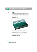
Страница 7: ...e on termination boards To close the signal circuit the isolated barriers are simply plugged in The isolated barriers can be replaced during live operation when the wiring is connected Figure 2 1 H Sy...
Страница 8: ...for all termination boards Each H System isolated barrier can therefore be mounted in each termination board slot HiC isolated barriers on HiC termination boards HiD isolated barriers on HiD terminat...
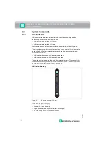
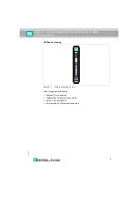
Страница 9: ...ons 2016 11 9 HiD Device Housing Figure 2 3 HiD device housing 18 mm Used for high channel density Compact 18 mm housing Highest channel density on the market Only 4 5 mm per channel For mounting on H...
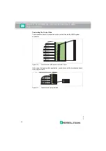
Страница 10: ...ation boards Once the isolated barrier is mounted the signal circuit between the field and control side is closed Figure 2 4 Connection example termination board with 16 slots Use For HiC or HiD isola...
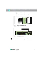
Страница 11: ...as one slot to mount a 32 channel HiD Mux2700 type HART multiplexer Preconfigured HART connection cables enable easy connection between the H System termination boards and the HART Communication Board...
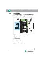
Страница 12: ...n Board and HART Communication Board Figure 2 7 Connection HART communication 1 Termination board 2 HART Communication Board 3 Connection power supply I and II redundant 4 Connection HART communicatio...
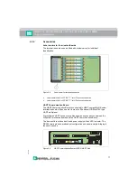
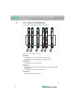
Страница 13: ...2 8 Connection via spring terminals Connecting the Power Supply and Fault Indication Output Isolated Barriers The isolated barriers are supplied via the termination board The isolated barriers are th...
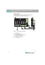
Страница 14: ...l Side The termination board is connected on the control side via the HIMA system connector Figure 2 10 Connection via HIMA system connector 96 pin In the case of a signal splitter application you can...
Страница 15: ...HART Communication Connect the HART communication via HART multiplexer as follows HART Plugs Figure 2 12 Connection via control side HART plugs HART Multiplexers Figure 2 13 HART multiplexer connectio...
Страница 16: ...ith a transistor output Digital Output Purple identifier 3 for solenoid drivers Analog Input Magenta identifier 4 for transmitter power supplies measuring transmitters and repeaters Yellow identifier...
Страница 17: ...ault failure display of causes detected outside the device inspection and elimination of fault required No fault Off No malfunction device is operating properly Yellow LED Switching states of binary i...
Страница 18: ...hort circuit status indicator 3 Green LED PWR Power supply status indicator OUT CHK PWR 1 2 3 LED Display function Display Meaning Green LED PWR1 Power supply I On Power supply OK Off No power Green L...
Страница 19: ...atus indicators 1 Green LED PWR1 Status indicator power supply I 2 Green LED PWR2 Status indicator power supply II 3 Red LED FAULT Device fault device failure power supply failure 4 Red LED Field Conn...
Страница 20: ...ifications 2 7 Label Carriers The isolated barriers are fitted with a label carrier ex works for individual identification Figure 2 17 Label carrier on the front 1 Label carrier on HiC devices for 35...
Страница 21: ...l UPR MR 35 mm x 15 mm 3 2 Mounting 3 2 1 Termination Board Mounting Warning Risk of short circuit Working on live parts can cause injuries and can compromise the function and the electrical safety of...
Страница 22: ...ounting rail runs centrally below the termination board 1 Clip the termination board 2 onto the DIN mounting rail 1 2 Tighten the mounting screws 3 The termination board 2 is now properly mounted and...
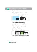
Страница 23: ...MA Installation 2016 11 23 Vertical and Horizontal Mounting Both mounting options are possible Unrestricted operation is possible across the entire temperature range of the system in each mounting dir...
Страница 24: ...2 above the contact elements of the termination board Note the connection direction of the device 3 Center the locking pins 3 above the locking elements of the termination board 4 Carefully push the d...
Страница 25: ...Danger Danger to life from incorrect installation Incorrect installation of cables and connection lines can compromise the function and the electrical safety of the device Observe the permissible cor...
Страница 26: ...Configuration of the isolated barriers Parameterize the DIP switches on the device side as follows 1 Remove the isolated barriers from the termination board as described in the Dismounting section 2...
Страница 27: ...the fault Device faults The isolators are designed so that internal faults are detected and reported In the case of a power failure the outputs are switched to a de energized state 4 2 Fault Output S...
Страница 28: ...at the output In the event of an fault the output will become highly resistive For this line fault transparency function corresponding input cards are required in the controller Figure 4 2 Example of...
Страница 29: ...the measurement and control technician an easy to measure standard signal common to all manufacturers Sensor signals are converted into standard signals via signal converters For more diagnostic optio...
Страница 30: ...tion 2 Carefully pull out the device from the contacts and locking elements Figure 5 1 Dismounting of an H System isolated barrier Danger Danger to life from using damaged or repaired devices Using a...
Страница 31: ...tion board 2 from the DIN mounting rail 1 Figure 5 2 Termination board fixing Warning Risk of short circuit Working on live parts can cause injuries and can compromise the function and the electrical...
Страница 32: ...ording to NE43 Current output HART compatible Current input HART compatible Digital output active or passive electronic output 100 mA 30 V short circuit protected Relay output 2 A minimum load 1 mA 24...
Страница 33: ...NAMUR The standards references for this interface have changed many times German standard old DIN 19234 Electrical distance sensors DC interface for distance sensors and switch amplifiers 1990 06 Euro...
Страница 34: ...ssover frequency Shock Resistance according to EN 60068 2 27 15 g 11 ms half sine 6 1 4 Mechanical Data Mounting Termination boards Snap on 35 mm DIN mounting rail according to EN 60715 Can be mounted...
Страница 35: ...HIMA sytem connector 96 pin HART plug if applicable Spring terminals if applicable Fire Protection Class Housing V2 according to UL 94 standard Unless stated otherwise all details relate to the refere...
Страница 36: ...l devices 2820 to 2860 Switch amplifiers 2871 to 2890 Solenoid drivers 2891 to 2900 Converters Special functions if available ES Version with increased safety HC Versions for long field wiring R1 Vers...
Страница 37: ...its safety parameters the pins are shortened at the factory Do not change the factory setting No Termination board Top view Isolated barrier Bottom view Type Safe area Hazardous area Hazardous area S...
Страница 38: ...pty position Insert polarizing pin Don t insert polarizing pin Pin to be trimmed Pin untrimmed Device side view Table 6 1 No Termination board Top view Isolated barrier Bottom view Type Safe area Haza...
Страница 39: ...E HiD2881 F HiD2061 HiD2062 HiD2071 HiD2072 HiD2821 HiD2822 HiD2824 HiD2842 HiD2844 G HiD2024 HiD2025 HiD2025SK HiD2026 HiD2026SK HiD2029 HiD2029SK HiD2030 HiD2030SK HiD2031 HiD2032 HiD2033 HiD2034 H...
Страница 40: ...zing pin Don t insert polarizing pin Pin to be trimmed Pin untrimmed Device side view Table 6 2 Note For more information see the corresponding datasheets No Termination board Top view Isolated barrie...
Страница 41: ...s for HIMA Technical Specifications 2016 11 41 6 4 Dimensions 6 4 1 Housing Designs for H System Isolated Barriers Figure 6 1 Figure 6 2 HiC Device Housings HiD Device Housings 12 5 mm 0 5 106 mm 4 17...
Страница 42: ...ecifications 6 4 2 Housing Types Termination Boards Figure 6 3 Figure 6 4 HiC Termination Boards for 16 Modules HiC Termination Boards for 32 Modules 266 mm 10 47 inch 163 mm 6 42 inch 253 mm 9 96 inc...
Страница 43: ...ecifications 2016 11 43 Figure 6 5 Figure 6 6 HiD Termination Board for 16 Modules HiD Termination Board for 16 Modules Housing Version 300 mm 11 81 inch 163 mm 6 42 inch 253 mm 9 96 inch 200 mm 7 9 i...
Страница 44: ...rl fuchs com PROCESS AUTOMATION PROTECTING YOUR PROCESS Worldwide Headquarters Pepperl Fuchs GmbH 68307 Mannheim Germany Tel 49 621 776 0 E mail info de pepperl fuchs com For the Pepperl Fuchs represe...