


1
2
3
4
TM060220
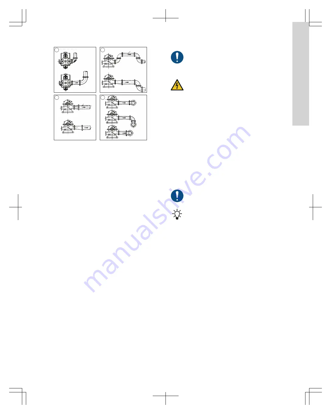
Fig.
Pipe arrangements
4
.6.2
Suction pipes
The inlet and outlet pipes must be of sufficient size and free of
internal foreign material.
Considerations for inlet pipes to achieve optimal performance are:
•
When operating under inlet pressure, pipe may be equal to, but
never less than, the inlet nozzle size.
•
Failure of the inlet pipe to deliver the liquid to the pump in this
condition can lead to noisy operation, swirling of liquid around
the suspended pump assembly, premature bearing failure and
cavitation damage to the impeller and inlet portions of the
casing.
Contact Peerless Pump for further information.
4
.6.3
Inlet valves and manifolds
Install isolation valves on the inlet and outlet pipes so that the pump
can be isolated for maintenance.
4
.6.4
Outlet valves
Install a non-return valve and an isolation valve in the outlet pipe.
The non-return valve protects the pump from backflow and
excessive backpressure. We recommend closing the isolation valve
before stopping or starting the pump.
Pump backspin and hydraulic shock can cause severe damage to
the pump and motor. To prevent this type of damage, install at least
one non-return valve in the outlet pipe, not more than 25 ft (7.5 m)
after the outlet flange.
If increasers are used on the outlet side of the pump to increase the
size of piping, place them between the non-return valve and the
pump.
If expansion joints are used, place them between the pipe anchor
and the non-return valve.
4
.6.5
Nozzle loads
Minimize pump nozzle loads by aligning the pipes with the pump
nozzles. Contact Peerless Pump for allowable nozzle load for your
particular system design.
4
.7
Lubrication, priming and cooling systems
If lubrication, priming and cooling systems are supplied, please see
additional documents attached to the pump or contact Peerless
Pump.
4
.8
Electrical
I
nstallation
All electrical connections must be carried out by a
qualified electrician in accordance with local regulations.
DANGER
Electric shock
Death or serious personal injury
‐
Switch off the power supply before you start any work
on the product.
‐
Make sure that the power supply cannot be switched
on accidentally.
Locate the electrical conduit and boxes so as to avoid obstruction of
the pump.
Check speed versus torque requirements during the starting phase
of a pump against the speed versus torque curve of the driving
motor.
In order to accelerate the pump up to rated speed, the driver should
be capable of supplying more torque at each speed than required
by the pump. In general, this condition is easily attainable with
standard induction or synchronous motors, except under certain
conditions when a motor with high pull-in torque may be required,
such as high specific speed pumps over 5000 US units (100 metric
units) or reduced voltage startup.
To achieve a smooth start for the pumping equipment, consider
connecting autotransformers to the starting panel or using solid-
state starters. These provide a gradual increase in voltage up to
rated voltage ensuring even acceleration.
4
.9
Control, monitoring, and alarm equipment
Check control and alarm systems for correct installation
and function according to the manufacturer's instructions.
Check all alarm point settings.
4
.9.1
Stopping the unit/reverse runaway speed
A sudden power and/or outlet valve failure during pump operation
against a static head will result in a flow reversal, and the pump will
operate as a hydraulic turbine in a direction opposite to that of
normal pump operation.
If the driver offers little resistance while running backwards, the
rotational speed may approach the pump-specific speed.
This condition is called runaway speed and causes mechanical
problems. Contact Peerless Pump for recommendations to prevent
this condition.
5
. Starting up the product
5
.1
Lubricating the pump
Before attempting to start the pump, check the following items:
•
lubrication fitting at packing, if applicable
•
lubrication for pump bearing
•
lubrication of the driver
•
oil-cooling connections for the driver, if applicable
Good practice includes the following:
•
Keep lubricant clean, and use a dust-tight cover on the storage
container.
•
Use the oldest lubricant first.
•
Clean the pump lubricant fittings before re-lubricating with
grease.
•
Use clean dispensing equipment.
1
3
English (US)