background image

PEAK Economizer Basic Model Quick Start

Guide

Overview

To set up your PEAK

®

 Economizer controller, perform the

following steps:

1.

Install the controller assembly with the included

installation instructions. Refer to the 

PEAK Economizer

Basic Model Product Data and Installation Guide

(LIT-12013281)

.

2.

Install additional sensors. The factory installs the

damper actuator and outdoor air sensor. You must

install any other sensors and output connections.

3.

Configure the controller using the local display.

4.

Run a Self-Test to verify proper operation.

Mounting the controller on a DIN rail

1.

Horizontally mount a 20 cm (8 in.) section of 35 mm

(1.3 in.) DIN rail.

2.

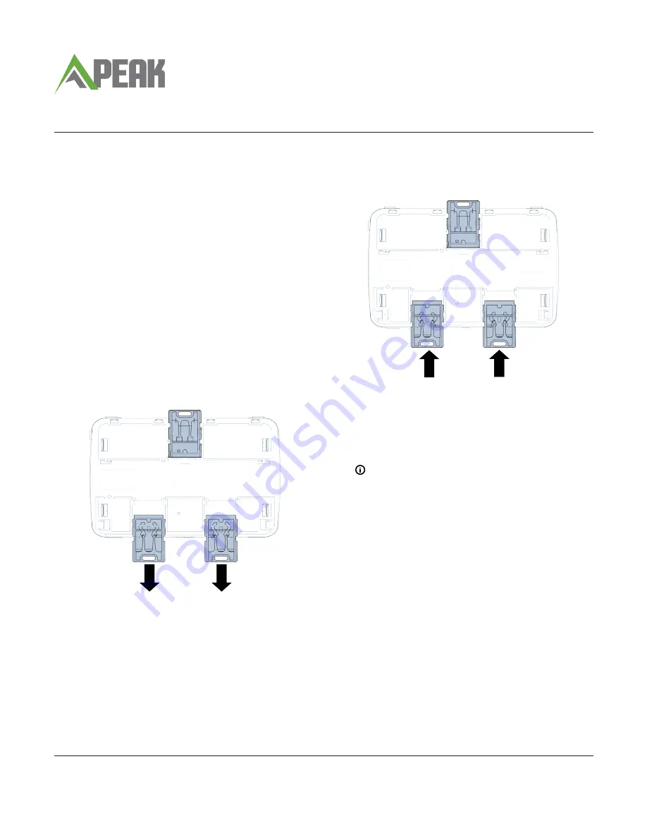
On the back of the controller, pull the two bottom

mounting clips outward (down).

Figure 1: Pull down lower mounting clips

3.

Place the controller on the DIN rail.

4.

Push the bottom mounting clips inward (up) to

secure the controller on the DIN rail.

Figure 2: Push up lower mounting clips

Wiring

1.  Connect the sensors to the inputs on the Economizer

controller.

2.  Use spade connectors to terminate the inputs and

outputs with the Spade termination.

Note: 

Temperature inputs accept a 10k

thermistor type 2 sensor. Humidity inputs

accept a 0 VDC to 10 VDC sensor.

3.  Use the Economizer wiring harness to connect the I/

O with the pin connector termination type.

4.  Install the sensors in the appropriate air stream.

*241014302090—*

24-10143-02090    Rev —

2019-08-28

(barcode for factory use only)

PK-ECO1001-0

Содержание Economizer Basic

Страница 1: ...section of 35 mm 1 3 in DIN rail 2 On the back of the controller pull the two bottom mounting clips outward down Figure 1 Pull down lower mounting clips 3 Place the controller on the DIN rail 4 Push the bottom mounting clips inward up to secure the controller on the DIN rail Figure 2 Push up lower mounting clips Wiring 1 Connect the sensors to the inputs on the Economizer controller 2 Use spade co...

Страница 2: ...on 1 Wiring harnesses 2 CD W00 00 2 zone CO2 sensor 3 24 VAC coil of exhaust fan or ERV relay or contactor 4 M9205 GGA EC01 actuator Table 1 Rooftop unit wiring example Callout Description 5 Rooftop unit control board 6 Conventional thermostat PEAK Economizer Basic Model Quick Start Guide 2 ...

Страница 3: ...on 1 Wiring harnesses 2 CD W00 00 2 zone CO2 sensor 3 24 VAC coil of exhaust fan or ERV relay or contactor 4 M9205 GGA EC01 actuator Table 2 Heat pump wiring example Callout Description 5 Heat pump control board 6 Conventional thermostat PEAK Economizer Basic Model Quick Start Guide 3 ...

Страница 4: ...ector SD Shutdown Status 24 VAC Pin Connector Table 3 Economizer controller terminations Name Description Type Termination Type OCC OCC Status 24 VAC Pin Connector Binary Outputs BOs ALM Alarm Output Alarm COM Relay dry contact Spade Y1O Cooling Stage 1 Relay 24 VAC Pin Connector Y2O Cooling Stage 2 Relay 24 VAC Pin Connector ERV EXH Exhaust Fan ERV Output Relay 24 VAC Pin Connector Additional Ter...

Страница 5: ... On 60 0 to 100 Table 5 Setup menu Level 2 on LCD Default values Available values Damper Fan Off 20 0 to 100 Damper Fan Off Lo Spd 40 0 to 100 Damper Fan On Lo Spd 80 0 to 100 Damper Fan Off Hi Spd 20 0 to 100 Damper Fan On Hi Spd 60 0 to 100 Vent Mode Disabled Disabled Controlled by IAQ Vent IAQ Stpt 1000 ppm 0 ppm to 2000 ppm Relearn System Relearns the sensors connected to the controller False ...

Страница 6: ...value IP IP SI Relearn System Relearns the sensors connected to the controller Default value False True False Self Test menu Table 10 Self Test menu Level 2 Level 3 Level 4 Description Self Test Status Current State Status Self Test Status Self Test Time Remaining Self Test Prompt N A Displays information about the test progress or any prompts that you need to answer All Test N A Runs all the test...

Страница 7: ...e any power supplied to the peripheral devices connected to binary outputs BOs Ambient conditions Operating 40 F to 158 F 40 C to 70 C 10 to 90 RH noncondensing UI Operating 4 F to 158 F 20 C to 70 C 10 to 90 RH noncondensing Storage 40 F to 194 F 40 C to 90 C 5 to 95 RH noncondensing Processor RX631 Renesas microcontroller Memory 2 MB internal program flash 32 KB internal E2Data flash 4 MB extern...

Страница 8: ...e separation between the equipment and receiver Connect the equipment into an outlet on a circuit different from that to which the receiver is connected Consult the dealer or an experienced radio TV technician for help Canada This Class B digital apparatus meets all the requirements of the Canadian Interference Causing Equipment Regulations Cet appareil numérique de la Classe B respecte toutes les...

Отзывы: