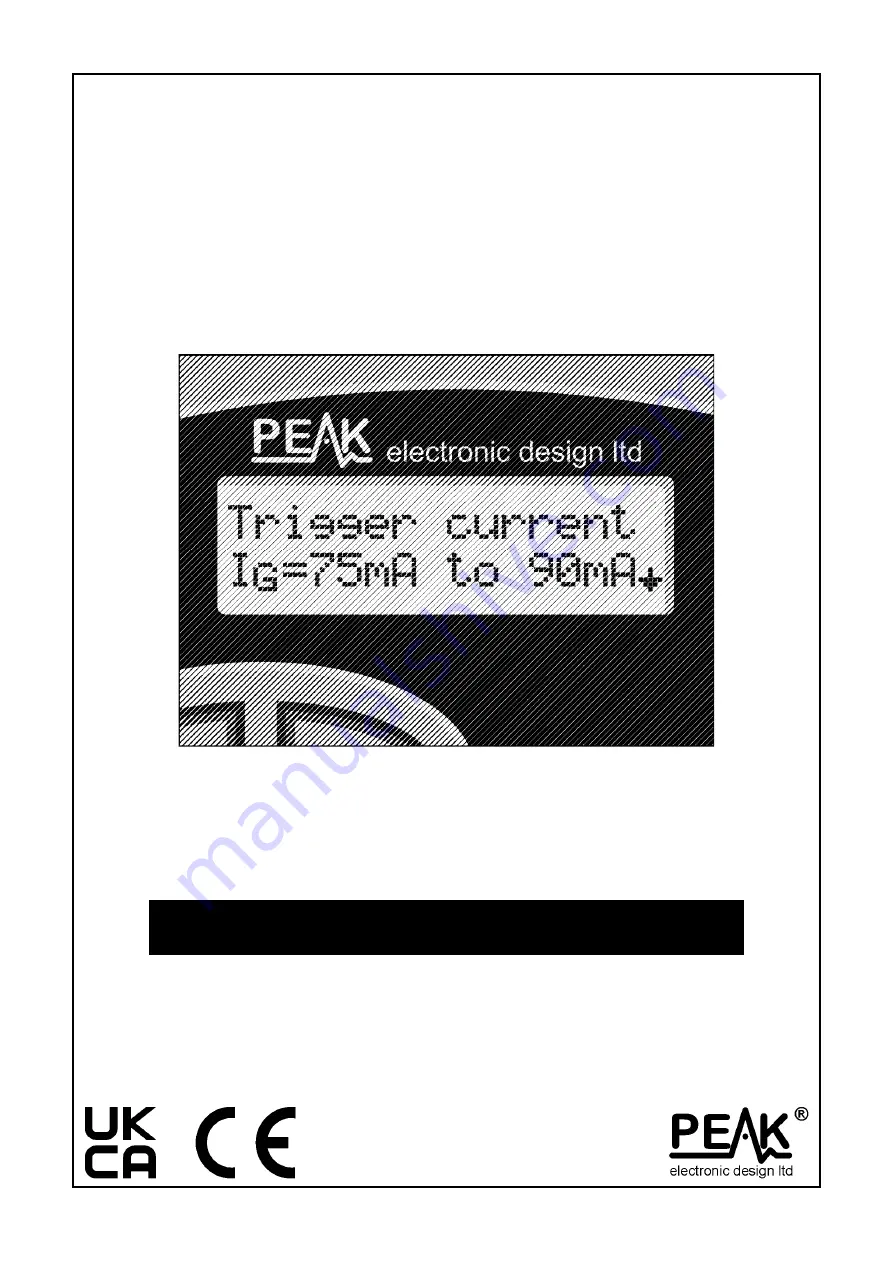
background image


Atlas SCR100 


Triac and Thyristor Analyser 


Model SCR100 

(Firmware: 4.0)


Designed and manufactured with pride in the UK


User Guide 


© Peak Electronic Design Limited 2004/2021 

In the interests of development, information in this guide is subject to change without notice. 

E&OE 

EN100-9 

Содержание Atlas SCR100

Страница 1: ...lyser Model SCR100 Firmware 4 0 Designed and manufactured with pride in the UK User Guide Peak Electronic Design Limited 2004 2021 In the interests of development information in this guide is subject to change without notice E OE EN100 9 ...

Страница 2: ...3 Safety Considerations 4 Analysing components 5 SCRs 6 Triacs 7 Notes on SCRs Thyristors and Triacs 8 Gate Sensitivity 10 Gate Voltage 11 Care of your SCR100 12 Battery Replacement 12 Self Tests 13 Appendix A Accessories 14 Appendix B Technical Specifications 15 Appendix C Statutory Information 16 This user guide has been written to accompany the SCR100 with revision 4 0 firmware Other revisions ...

Страница 3: ...atures Automatic component identification Thyristor or Triac Automatic pinout identification Displays actual trigger gate current classification Measures gate voltage during trigger Fixed load current of 100mA Unique automatic boost function ensures a device test voltage of 12V regardless of battery condition Suitable for devices requiring gate currents up to 90mA Automatic and manual power off ...

Страница 4: ... to the SCR100 and invalidation of the manufacturer s warranty Analysis of discrete unconnected components is recommended The SCR100 is designed to provide accurate and reliable information for the majority of supported component types SCRs and Triacs as described in this user guide Testing of other component types or component networks may give erroneous results and may also cause damage It is im...

Страница 5: ... the results of the analysis are displayed Information is displayed a page at a time each page can be displayed by briefly pressing the scroll off button If the SCR100 cannot recognise the component connected to the test probes or the component under test is outside the specifications covered by this instrument the following message will be displayed Note An arrow symbol on the display indicates t...

Страница 6: ...Pressing the scroll off button will then display the pinout details for the device In this example the Anode of the SCR is connected to the Red test clip the Cathode is connected to the Green test clip and the Gate terminal is connected to the Blue test clip The gate trigger current is displayed on the next screen Note that SCRs are often only specified to have a certain maximum trigger current th...

Страница 7: ...nnected to the Green test clip and the Gate terminal is connected to the Blue test clip The gate trigger current is displayed on the next screen Note that Triacs are often only specified to have a certain maximum trigger current the actual measured trigger current may be well below that value The gate trigger current1 displayed is that for quadrant 3 Quadrant 1 will usually be very similar The loa...

Страница 8: ...red by a pulse of current to the control gate terminal Once triggered the SCR will continue to conduct current in the forward direction between the anode and the cathode until the device is turned off SCR Turn Off In order to turn off a triggered SCR it is necessary to reduce the anode cathode load current below the holding current for typically 5 200 s Shorter periods may leave insufficient time ...

Страница 9: ...nnections MT1 and MT2 The device is switched to the on state by a current into or out of the gate terminal with respect to the MT1 terminal Once triggered main load current will continue to flow until a zero cross in the mains cycle is encountered at this point the device switches off Therefore if the device is to be kept on a continuous gate current must be provided or at least a gate current pul...

Страница 10: ...igger level 5 35mA Trigger level 6 50mA Trigger level 7 60mA Trigger level 8 75mA Trigger level 9 90mA As an example a reported trigger current of 10 25mA means that device triggering occurred at a gate current of 25mA but not at 10mA Therefore the trigger current for the device under test is between 10mA and 25mA Although Triacs are tested in both quadrants 1 and 3 the reported gate trigger curre...

Страница 11: ...pper end of the displayed gate trigger current For example if the gate sensitivity is shown as 35 to 50mA then the displayed gate voltage will be the voltage measured during a gate current of 50mA The gate voltage may also be dependent on the load current for the SCR100 the load current is fixed at 100mA higher load currents may result in a higher gate voltage The load current at which SCRs and Tr...

Страница 12: ...r to achieve the target of 12V and the following may be displayed If the boost function cannot generate the required test voltage then the following message is displayed Replacement of the battery is then mandatory The SCR100 will not continue to operate if this condition is encountered Battery type AAA cell Alkaline NiMh or Lithium Iron Disulphide Battery access To replace the battery place the u...

Страница 13: ...ts a message will be displayed and the unit will switch off automatically If the problem was caused by a temporary condition such as applying power to the test clips then simply restarting the SCR100 may clear the problem If a persistent problem does arise it is likely that damage has been caused by an external event such as excessive power being applied to the test clips or a large static dischar...

Страница 14: ...s ideal for protecting your SCR100 and probes There is even space for spare batteries and this user guide Replacement Probes If your probes become damaged you may wish to purchase a new set of probes Replacement Battery Replacement Alkaline AAA batteries are available from Peak Electronic Design Limited your local agent or any good electronics store All accessories are available from Peak Electron...

Страница 15: ... s 275 s 300 s Load pulse width IGT 100 A 1000 s 1100 s 1200 s Load pulse width IGT 100 A 460 s 510 s 560 s Battery type AAA 1 5V Alkaline Battery voltage range 1 0V 1 5V 1 7V Low battery warning 1 1V Battery life Typically 1600 operations 6 Inactivity power down period 15 seconds if no result found 60 seconds if result found Dimensions enclosure 103 x 70 x 20 mm Operating temperature range 15 C 3...

Страница 16: ...ical damage or abuse d Normal wear and tear The customer s statutory rights are not affected by any of the above All claims must be accompanied by a proof of purchase WEEE Waste of Electrical and Electronic Equipment Recycling of Electrical and Electronic Products It is not permissible to simply throw away electrical and electronic equipment Instead these products must enter the recycling process ...

Отзывы: