background image


www.pdrl.in 

19 | 

P A G E                                           A E R O F C   U S E R   M A N U A L    


3.5


M

OUNTING 

P

ROCEDURE


o


Mount the AeroFC on your drone using the 3M double layer tape or screws provided with 
the package. 

o


Stick the 3M double layer tape at the bottom of AeroFC (refer diagram A) OR screw the 
AeroFC to the mounting plate of the drone (refer diagram B). 


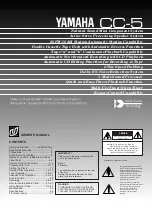
Image #8: AeroFC enclosure mounting process #1 


o


Make sure that the logo on the flight controller is pointing to the front of your drone as 
shown in the following image: 


Image #9: AeroFC enclosure mounting process #2 

Содержание AeroFC

Страница 1: ...User Manual AeroFC Autopilot ...

Страница 2: ...op Cover Details 6 2 1 2 2 Bottom Cover Details 7 2 1 3 Screws Used 7 2 1 4 Power Specifications 7 2 1 5 PIN Descriptions 8 2 1 5 1 Telem_1 8 2 1 5 2 UART_4 8 2 1 5 3 Telem_2 8 2 1 5 4 CAN_2 8 2 1 5 5 CAN_1 9 2 1 5 6 GPS and Safety 9 2 1 5 7 I2C_2 9 2 1 5 8 I2C_1 9 2 1 5 9 Power_2 10 2 1 5 10 Power_1 10 2 1 5 11 ADC 10 2 1 5 12 SPI_5 10 2 1 5 13 DSM SBUS RSSI 11 2 1 5 14 SBUS_OUT 11 2 1 5 15 I2C_3...

Страница 3: ...n Sequence 20 4 Configuration 21 4 1 In Built Firmware 21 4 2 Ground control Station Software Download 21 4 2 1 Mission Planner 21 4 2 2 AeroGCS 21 4 2 3 Qgroundcontrol 21 4 3 Connecting with Ground Control Station 21 4 4 First Boot 22 5 Warranty and Support 22 5 1 Limited warranty 22 5 1 1 What is covered 22 5 1 2 What is Not covered 22 5 1 3 What is warranty period 23 5 1 4 Who is covered 23 5 1...

Страница 4: ...r Anil Chandaliya Review Date 12th February 2020 Document Number PDRL Public AeroFC 2020 01 Protective Marking Public Document Document classification User Manual Distribution List Name Job Title Email Id Public Document Public Document Public Document Document History Version Number Author Date of Release Summary of Changes v 1 0 Saurabh Joshi 01 02 2020 Initial Document ...

Страница 5: ...fter quick start guide Image 6 AeroFC packaging box component layout Image 7 AeroFC internal component structure Image 8 AeroFC enclosure mounting process 1 Image 9 AeroFC enclosure mounting process 2 Image 10 AeroFC components connection diagram Image 11 AeroFC laptop tab connection Image 12 AeroFC first boot image using Mission Planner 1 2 ABBREVIATIONS USED IN THIS DOCUMENT Here are the abbrevi...

Страница 6: ...ro BMI055 Magnetometer IST8310 Barometer MS5611 Power Supply Connection 2 Power Source with automatic failover Power Consumption Power 4 3 5 4V USB Input 4 75 5 25V Servo Rail Input 0 36V Interfaces o 8 14 PWM outputs 6 from IO 8 from Main controller o Dedicated PWM Capture inputs on Main Controller o Dedicated R C input for CPPM o Dedicated R C input for PPM and S Bus o Analog PWM RSSI input o S ...

Страница 7: ...duct dimension are as below a Height Outer height of the AeroFC is 29mm b Length Outer length of the AeroFC enclosure is 103mm c Width Outer width of the AeroFC enclosure is 50 50 mm d Mounting Screw Mounting screw 2x5 mm 2 1 2 1 Top Cover Details Image 1 AeroFC Enclosure Dimension ...

Страница 8: ...Make and Model PAN head Philips machine screws Dimension M2x8mm Material Stainless steel Quantity 4pcs 2 1 4 Power Specifications o Operating power 4 3 5 4 V o USB Input 4 75 5 25 V o High power servo rail up to 36 V servo rail does not power the autopilot o Dual voltage and current monitor inputs o It supports triple redundant power input if power input is provided to both battery inputs and the ...

Страница 9: ... 5 RTS Request to send line 6 GND Ground 2 1 5 2 UART_4 Pin Name Description 1 5V VCC 2 Tx Transmitter pin 3 Rx Receiver pin 4 SCL2 Clock line 5 SDA2 Data line 6 GND Ground 2 1 5 3 Telem_2 Pin Name Description 1 5V VCC 2 Tx Transmitter line 3 Rx Receiver line 4 CTS Clear to send line 5 RTS Request to send line 6 GND Ground 2 1 5 4 CAN_2 Pin Name Description 1 5V VCC 2 CAN_H CAN HIGH line ...

Страница 10: ...round 2 1 5 6 GPS and Safety Pin Name Description 1 5V VCC 2 Tx Transmitter line 3 Rx Receiver line 4 SCL1 Clock line 5 SDA1 Data line 6 Safety_SW Safety switch pin 7 Safety_SW_LED Safety switch LED 8 Safe_VCC VCC 9 Buzzer Buzzer pin 10 GND Ground 2 1 5 7 I2C_2 Pin Name Description 1 5V VCC 2 SCL2 Clock line 3 SDA2 Data line 4 GND Ground 2 1 5 8 I2C_1 Pin Name Description 1 5V VCC ...

Страница 11: ...rrent Clock line Current pin 4 SDA1 Voltage Data line Voltage pin 5 GND Ground 6 GND Ground 2 1 5 10 Power_1 Pin Name Description 1 Power_IN Input power 2 Power_IN Input power 3 Current Clock line 4 Voltage Data line 5 GND Ground 6 GND Ground 2 1 5 11 ADC Pin Name Description 1 5V VCC 2 3V3 ADC ADC pin 3 6V6 ADC ADC pin 4 GND Ground 2 1 5 12 SPI_5 Pin Name Description 1 5V VCC 2 SCK Clock line ...

Страница 12: ...SBUS RSSI Pin Name Description 1 5V VCC 2 DSM SBUS RC 3 RSSI 4 DSM 3V3 5 GND Ground 2 1 5 14 SBUS_OUT Pin Name Description 1 NC Not connected 2 SBUS_OUT 3 GND Ground 2 1 5 15 I2C_3 Pin Name Description 1 5V VCC 2 SCL3 Clock line 3 SDA3 Data line 4 GND Ground 2 1 5 16 Debug and UART_7 Pin Name Description 1 5V Vcc 2 Debug_Tx Transmitter line 3 Debug_Rx Receiver line 4 FMU_SWDIO Data line ...

Страница 13: ...gs AeroFC AutoPilot can be triple redundant on the power supply if three power sources are supplied The two power rails are POWER1 POWER2 and USB The output power rails FMU PWM OUT and I O PWM OUT 0V to 36V do not power the flight controller board and are not powered by it You must supply power to one of POWER1 POWER2 or USB or the board will be unpowered Normal Operation Maximum Ratings Under the...

Страница 14: ...www pdrl in 13 P A G E A E R O F C U S E R M A N U A L 2 2 PRODUCT BLOCK DIAGRAM Image 3 AeroFC Autopilot Block Diagram ...

Страница 15: ...R M A N U A L 3 INSTALLATION 3 1 UNPACKING THE BOX 3 1 1 AeroFC Box First view Image 4 AeroFC Packaging Box cover with Quick Start Guide 3 1 1 1 View after removal of Quick start guide Image 5 AeroFC packaging box cover after quick start guide ...

Страница 16: ...www pdrl in 15 P A G E A E R O F C U S E R M A N U A L 3 1 1 2 View of other components in package Image 6 AeroFC packaging box component layout ...

Страница 17: ...N WHILE HANDLING o Only trained and qualified personnel should be allowed to install replace or service this equipment o To prevent the system from overheating do not operate it in an area that exceeds the maximum recommended ambient temperature of 50 C o Non static environment ...

Страница 18: ... Type USB Cable for Communication between AeroFC and Ground 4 Buzzer alarming buzzer 5 Safety Switch for arming device safely 6 Mounting Tape to stick flight controller on airframe 7 Mounting Screws to mount flight controller on airframe 8 I2C Cables for connection of I2C devices 9 I2C PCB for expansion of I2C PCB 10 Power Module Cable to power up flight controller board ...

Страница 19: ...www pdrl in 18 P A G E A E R O F C U S E R M A N U A L 3 4 INSIDE THE ENCLOSURE Image 7 AeroFC internal component structure ...

Страница 20: ... the package o Stick the 3M double layer tape at the bottom of AeroFC refer diagram A OR screw the AeroFC to the mounting plate of the drone refer diagram B Image 8 AeroFC enclosure mounting process 1 o Make sure that the logo on the flight controller is pointing to the front of your drone as shown in the following image Image 9 AeroFC enclosure mounting process 2 ...

Страница 21: ...wed for connecting the devices peripherals sensors 1 Connect power module to the power port of board 2 Connect the AeroFC board to the computer tab using USB cable 3 Connect the safety switch 4 Connect the buzzer 5 Connect the GPS AeroFC board 6 Connect the RC receiver to PPM pins of the board 7 Connect the lidar to any I2C ping of the board 8 Connect 360 degree Lidar to any UART port of the devic...

Страница 22: ...issionPlanner MissionPlanner latest msi 4 2 2 AeroGCS You can download the PDRL AeroGCS from its official website as mention below http pdrl in aerogcs ground control software 4 2 3 Qgroundcontrol You can download the PX4 Qgroundcontrol from its official website as mention below http qgroundcontrol com downloads 4 3 CONNECTING WITH GROUND CONTROL STATION Connect the AeroFC board to laptop using C ...

Страница 23: ... warranty covers defects in materials and workmanship in this product 5 1 2 What is Not covered This limited warranty does not cover any damage deterioration or malfunction resulting from any alteration modification improper or unreasonable use or maintenance misuse abuse accident neglect exposure to excess moisture fire improper packing and shipping such claims must be presented to the carrier li...

Страница 24: ... 5 1 6 What PDRL will not do In order to get the warranty of the AeroFC it is necessary to ship the product to PDRL or its authorized partner s The cost of shipping of part and its insurance will not be taken care by PDRL As well the responsibility to deliver the product to PDRL will not lie with PDRL 5 1 7 How to obtain warranty To obtain a remedy under this limited warranty customer should conta...

Страница 25: ... Only devices under AMC would be entitled to have technical support post one month of delivery h Customer can seek help related to configuration issues or any errors related to the AeroFC device 5 3 PRODUCT LICENSE AND COMPLIANCES AeroFC is an open hardware design following the OSHW 1 1 definition licensed under the Creative Commons Attribution ShareAlike 3 0 Unported CC BY SA 3 0 license The sche...

Отзывы: