Status: 06/2013
Operating
Instructions
P
lease
keep
careful!
P
lease
keep
careful!
Paul Wärmerückgewinnung GmbH
August-Horch-Straße 7
08141 Reinsdorf
Tel.: +49(0)375 - 303505 - 0
Fax: +49(0)375 - 303505 - 55
Germany
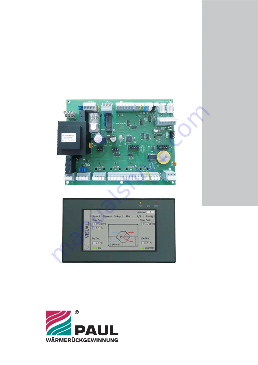
TAC4 DG + GRC
Control unit
Installation and maintenance


