19
F
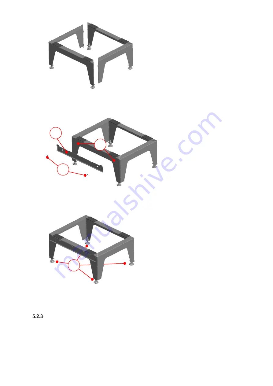
Fig. 16: Two sets of base parts fixed together
4. Mount the fastening sheet
C
on the long base part with the lugs pointing upwards. To do this, screw the two
Parker screws
D
into the holes provided
E
on the base part so that they go through the fastening sheet.
Fig. 17: Mounting the fastening sheet on the base part
5. Now use the height-adjustable feet
F
to adjust the fully assembled floor stand on the designated set-up area
so that it is plumb vertical and stable. Then fix it in this height position with the lock nuts of the adjustable feet.
Fig. 18: Aligning the floor stand
6. Place the FOCUS unit on the floor stand so that the lugs of the fastening sheet hook into the slots in the lock
seam at the bottom of the unit's rear cover. See Fig. 12.
Connecting the ventilation tubes
The following points must be observed when installing the ventilation tubes:
•
Attach the different types of ventilation tube provided with the ventilation system to the relevant connectors
according to whether the unit is the LEFT- or RIGHT-hand version (see air connections sticker on control
cover plate).
C
E
D
Содержание FOCUS 200 Base
Страница 1: ...Translation of the original instruction manual Heat Recovery Unit FOCUS 200 Base...
Страница 30: ...30 Dimensions Fig 33 Dimensional drawing...
Страница 31: ...31 FOCUS 200 Base terminal scheme Fig 34 Terminal assignment terminal plan...
Страница 36: ...36 PDE Manual_Focus 200 Base_V1 1 V1122 DE Subject to change...


