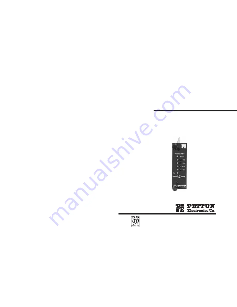
background image

USER

MANUAL

MODEL 1180RC and
1184RC 

Single Fiber

Rack Card Modem

SALES OFFICE
(301) 975-1000
TECHNICAL SUPPORT
(301) 975-1007
http://www.patton.com

07M1180RC-D
Doc# 017031UD
Revised 03/11/99

C E R T I F I E D

An ISO-9001

Certified Company

Содержание 1180RC

Страница 1: ...L 1180RC and 1184RC Single Fiber Rack Card Modem SALES OFFICE 301 975 1000 TECHNICAL SUPPORT 301 975 1007 http www patton com 07M1180RC D Doc 017031UD Revised 03 11 99 C E R T I F I E D An ISO 9001 Ce...

Страница 2: ...cur in a particular installation If the Model 1180RC 1184RC does cause interference to radio or televi sion reception which can be determined by turning the power off the user is encouraged to try to...

Страница 3: ...ver a single optical fiber Mounting in Patton s cluster box and 1000R16P rack sys tem the Model 1180RC supports synchronous data rates to 256 Kbps and asynchronous data rates to 38 4 Kbps and the Mode...

Страница 4: ...l 1180RC and Table 1A Model 1184RC which shows each possible data rate and switch settings Important When the data rate is followed by dbl the space between data packets is doubled This means communic...

Страница 5: ...RTS CTS Off Standard Modem default settings S2 4 S2 5 S2 6 Not Used S2 7 S2 8 RS 232 Loopback Control The Model 1180RC 1184RC gives you the option of enabling test modes via the front panel toggle sw...

Страница 6: ...e socket the arrow should always point toward the front panel of the PC board 3 2 REAR CARD CONFIGURATION The Model 1180RC 1184RC is compatible with four single fiber rear interface cards Figure 4 bel...

Страница 7: ...lifted from frame ground JB3 Position 1 2 DTE Shield DB 25 Pin 1 or M 34 Pin A and FRGND Connected Position 2 3 DTE Shield DB 25 Pin 1 or M 34 Pin A and FRGND Not Connected Signal Ground Frame Ground...

Страница 8: ...LING THE MODEL 1180RC 1184RC INTO THE CHASSIS The Model 1180RC 1184RC is comprised of a front card and a rear card The two cards meet inside the rack chassis and plug into each other via mating 50 pin...

Страница 9: ...cables you are ready to operate the units This section describes the LED status monitors the power up procedure and the use of the built in test modes 5 1 LED STATUS MONITORS The Model 1180RC 1184RC...

Страница 10: ...rform a BER bit error rate test on the system using exter nal test equipment 4 Perform a BER test on each unit If the BERT test equipment indicates no faults and the data terminal indicates a fault fo...

Страница 11: ...180RC 1184RC are configured the same way Fiber link is con Check the ST or SMA nected improperly connection on the back of both Model 1180RC 1184RC RS 232 V 35 connec Check RS 232 V 35 tions are fault...

Страница 12: ...4RC Transmit Data B 14 From 1180RC 1184RC Receive Data B 16 B F L R V Z DD NN A E K U Y CC HH MM D J N T X BB FF LL H M S W AA EE KK A JJ P Frame Ground A Request to Send C Data Set Ready E Data Termi...

Страница 13: ...vity Minimum 0 12 A w LED Indicators TD RD RTS CD Power Test Diagnostics Local and remote loopback Connectors DB 25 female RS 232 V 35 ST or SMA fiber M 34 female V 35 Dimensions 4 127 W x 1 52 H x 5...

Отзывы: