

C58/20-HF
PLAFONIERA 2-VIE 20W
20W 2-WAYS CEILING SPEAKER
Connessioni
I collegamenti devono essere realizzati con linea di
distribuzione a tensione costante.
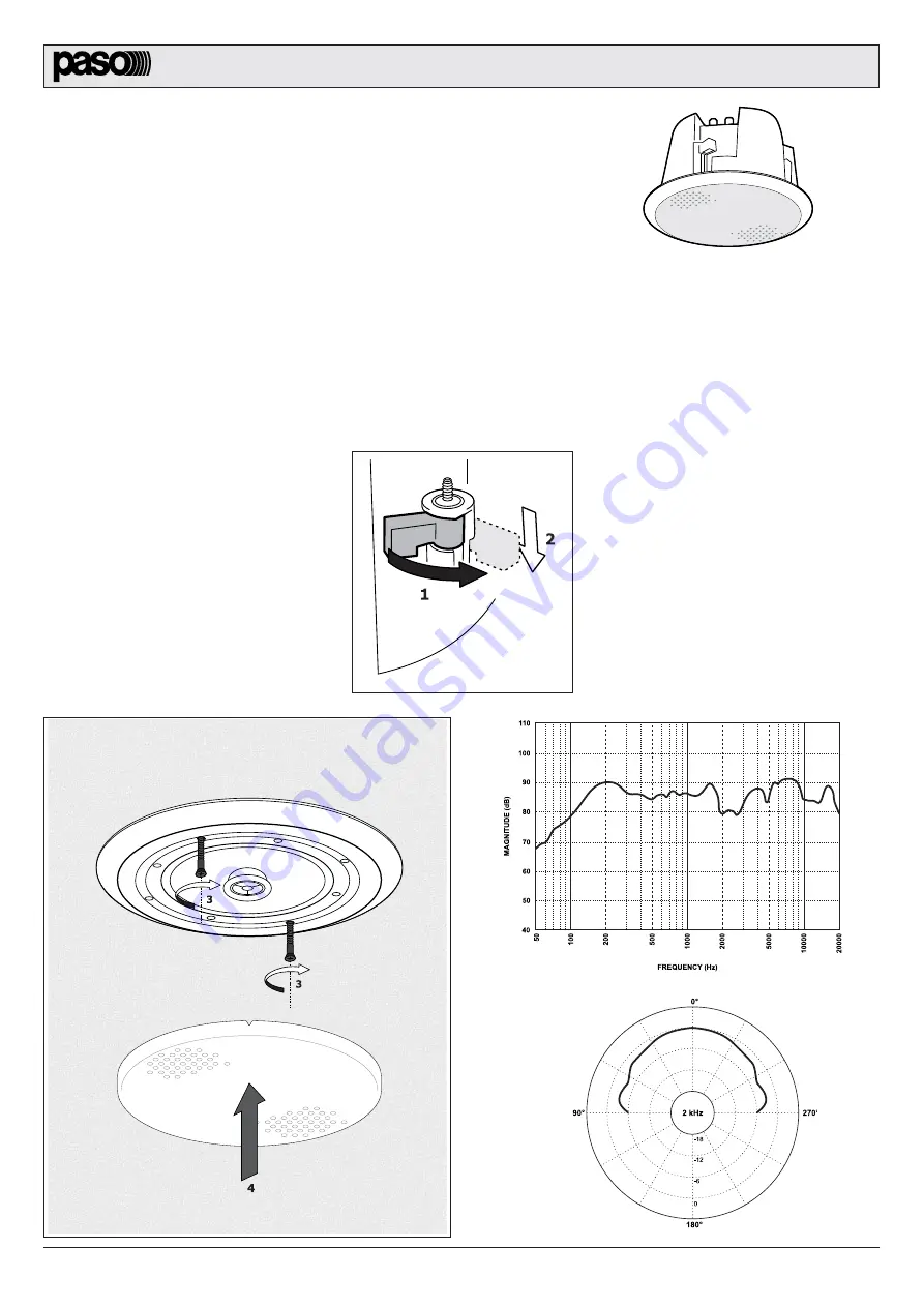
Procedura di montaggio
Per prima cosa, eseguire il foro nel controsoffi tto (Ø170
mm); quindi, procedere come segue:
1) ruotare due dei quattro ganci verso l’esterno e
sganciare la griglia dal corpo del diffusore spingendoli
verso il basso come illustrato in fi g. 1.
2) collegare i cavi provenienti dalla linea di distribuzione
al diffusore (0
colore nero, 100V colore rosso);
3) dopo aver riportato i ganci nella posizione originaria,
inserire la plafoniera nel foro e serrare a fondo le
viti (fi g. 2);
4) riposizionare quindi la griglia forata sul diffusore.
Note di sicurezza
Leggere attentamente il presente foglio istruzioni. La PASO declina ogni
responsabilità per danni a persone e/o cose derivanti dalla non corretta
installazione e dall’uso improprio del prodotto. La messa in opera del diffusore
deve essere effettuata da personale addestrato: un’errata installazione
potrebbe comportare il rischio di scossa elettrica.
Istruzioni per il montaggio
La plafoniera C58/20-HF è stata realizzata completamente in ABS; il
particolare sistema di fi ssaggio permette di ridurre notevolmente i tempi
d’installazione.
Fig. 2
Mounting instructions
The C58/20-HF ceiling speaker is made entirely of ABS; the particular fi xing
system allows to reduce considerably installation time.
Safety notes
Please read this instruction sheet carefully. PASO will accept no liability for
personal injury and/or damage to property resulting from incorrect installation
or improper use of the product. The speaker unit must be set up by trained
personnel. Incorrect installation could result in the risk of electric shocks.
Connections
The connections must be made to a constant-voltage
distribution line.
Mounting procedure
At fi rst, make the hole in the ceiling (Ø170 mm) and
then follow these steps:
1) turn outside two of the four hooks and release the
body of the speaker grille by pushing them down
as shown in fi gure 1.
2) connect the wires from the distribution line to the
speaker (0
black color, 100V red colour);
3) after reporting the hooks in the original position,
place the fi xture into the hole and tighten the
screws (fi gure 2);
4) reposition the grid hole in the speaker.
Fig. 1