


Installation of the individual drive PSD1-S
32 (109)
192-011006N8 2019-07
09.10.19 09:27
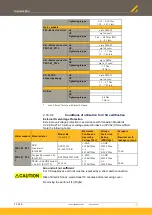
Status
No.
Status of axis
Left LED a
(green) (ready)
Right LED b
(red) (error)
14
Axis energized
on
Single flash
15
Axis de-energized
HEDA3 slave not ready
off
Double flash
16
Axis energized
HEDA3 Slave not ready
on
Double flash
17
Axis de-energized
HEDA3 Master not ready
off
Triple flash
18
Axis energized
HEDA3 Master not ready
on
Triple flash
19
Axis de-energized
off
Jitter (10 HZ)
20
Axis energized
on
Jitter (10 HZ)
Error response 1: Ramping with slow ramp; then deactivate control loops.
Error response 2: Ramping with "Stop" ramp, then deactivate control loops.
For the meaning of individuals errors please go to Error list.
Single flash
Double flash
Triple flash
Caution - Risk of electric shock!
High voltage supply may be present even with missing voltage supply (both
LEDs off)!
4.5
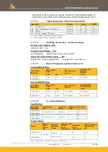
X17: Digital Inputs / outputs (PSD1-S)
Pin X17
Input / Output
1
Input
+24 VDC Devices - Control voltage
2
Input
GND24V
3
Input
+24 VDC for digital outputs
4
I0
Input 0
5
I1
Input 1
6
I2
Input 2
7
I3
Input 3
8
GND24V
9
O0
Output 0
10
GND24V
11
A1
Output 1
12
STOA/
STO Channel A Input
13
factory use
14
STOGND
STO Ground
15
factory use
16
STOB/
STO Channel B input
Loading of the outputs: Maximum 200 mA
In case of overload / over-temperature the output is deactivated and reactivated
automatically after cooling.
All inputs and outputs do have 24 V level.
Input level:
"0" (low) = Rated Input Voltage
≤
12.5 V
"1" (high= Rated Input Voltage
≥
13.5 V
The digital outputs are free for writing via object 0x2079.0x01 or 0x60FE.0x01 via
fieldbus.
The status of digital inputs can be read via object 0x2070.0x00 or 0x60FD.0x00 .