background image

Parker ISOBUS Suite – User Manual 

36/44 


Contents


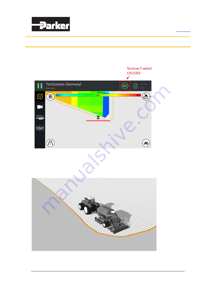
ISOBUS Task Controller (TC) has an 

SC

 button in the top bar of the main page to enable or 

disable Section Control. 


Figure 54. Turn Section Control ON or OFF 

In the ISOBUS Task Controller (TC), the field is defined as a polygon. In fact, this field is internally 

divided into a grid. Each cell in the grid stores data if any work has been done in the cell (if the 

device has applied product to the cell). 


Figure 55. The field is defined as a polygon with a grid inside 


4.  Section Control 

Содержание MSG17-4830-UK

Страница 1: ...User Manual PARKER ISOBUS SUITE Publ No MSG17 4830 UM UK Edition 02 2021...

Страница 2: ...INJURY AND PROPERTY DAMAGE This document and other information from Parker Hannifin Corporation its subsidiaries and authorised distributors provide product and or system options for further investiga...

Страница 3: ...3 Complete Task Setup 17 2 4 Run Task 17 2 5 Task Totals 19 2 6 Complete Task 21 2 7 Export Task 21 2 8 Eject USB Thumbdrive 25 3 Map View 26 3 1 Map Zoom Modes 26 3 2 Steering Guidance 27 3 2 1 Guid...

Страница 4: ...Parker ISOBUS Suite User Manual 4 44 Contents ISOBUS Universal Terminal UT Figure 1 ISOBUS UT overview 1 Overview List of implements Data Mask Soft keys...

Страница 5: ...or has multiple universal terminals UT connected each UT needs to have a unique VT Number defined The number can be changed in this field Localisation Define language and units of measurements Under S...

Страница 6: ...roller ISOBUS TC application Figure 3 Precision Farming Workflow 1 1 Main Page View When the ISOBUS Task Controller TC app is started the main page is loaded first The user settings are also loaded se...

Страница 7: ...ISOBUS TC main page The task setup page allows user to select the task see an overview of the task and task totals The task setup page also provides functionalities to create a new task clear all tas...

Страница 8: ...on on the taskdata files as well as the functionality to eject unmount USB media Figure 7 Enter task import export page Figure 8 Task import page view On the right side of the page the list of existin...

Страница 9: ...t is not possible to import a single task from the taskdata file that contains multiple tasks The user interface indicates the importing state for the taskdata file with different colors as follows To...

Страница 10: ...e progress of taskdata import After a successful completion the user is returned to the task setup page Figure 11 Task import completed After user has imported or created new tasks all tasks are shown...

Страница 11: ...xport taskdata file see chapter Export Task 2 2 Task States A small symbol next to each task name shows the current state of the task There are 4 different states defined new task paused task running...

Страница 12: ...uires user attention or action The task configuration page provides functionalities to define task basic information define system layout and assign device product and rate control Figure 15 Task conf...

Страница 13: ...ure 16 Device layout setup view If the tractor has a front ISOBUS connector there is an empty space in front of the tractor and devices can be dragged to this position When dragging the device all com...

Страница 14: ...the connector type is unknown 2 3 2 Product Assignment Product assignment view allows user to select a product for each device function Devices that support multiple products functions have tabs for...

Страница 15: ...t below the device will control the whole field with this value Off mode is intended for the situations where the user wants to adjust the rate manually from the universal terminal UI Figure 20 Produc...

Страница 16: ...Parker ISOBUS Suite User Manual 16 44 Contents Figure 21 Fixed rate control Figure 22 Devices with multiproduct support...

Страница 17: ...can be completed for the selected task Figure 24 Complete task setup 2 4 Run Task To run a task go to task setup page and select a task from the list shown on left side A previously completed task ca...

Страница 18: ...SOBUS Suite User Manual 18 44 Contents Figure 25 Select a task The name of the selected task is now displayed at the top The task can now be run or paused from the button in the upper left corner of t...

Страница 19: ...r TC collects task totals data when task is running Task totals can be viewed from the main page by clicking the task totals button or on the task setup page by clicking the Totals tab The task totals...

Страница 20: ...Parker ISOBUS Suite User Manual 20 44 Contents Figure 27 Task totals view from main page Figure 28 Task totals view on task setup page...

Страница 21: ...ompleted Figure 29 Complete the task However the completed tasks can be continued simply by running them again the status of the task is set to running 2 7 Export Task On the task setup page click the...

Страница 22: ...e that contains multiple tasks The task does not need to be marked complete in order to be exported Taskdata file can be exported as default taskdata Fixed path USB TASKDATA TASKDATA xml Taskdata file...

Страница 23: ...Parker ISOBUS Suite User Manual 23 44 Contents To export the taskdata follow the steps described in Figure 32 Figure 35 Figure 32 Export task step 1 Figure 33 Export task step 2...

Страница 24: ...Parker ISOBUS Suite User Manual 24 44 Contents Figure 34 Export task step 3 Figure 35 Export task step 4...

Страница 25: ...Parker ISOBUS Suite User Manual 25 44 Contents 2 8 Eject USB Thumbdrive If you want to eject unmount USB thumbdrive follow the next steps Figure 36 Export task step 5 Figure 37 Export task step 6...

Страница 26: ...a button In field view the map zoom level is automatically set to fit the whole field In field view zoom level can be changed by using the pinch gesture In tractor view the map zoom level is fixed to...

Страница 27: ...n provides steering guidance functionalities as a part of the map view The guidance provides user steering correction information for a line that is aligned with calibrated A and B points The system a...

Страница 28: ...ance lines Enter A B line teaching The texts on both buttons Width m and Teach must be green for guidance to be switched on Working width is automatically set by the widest device and it can be manual...

Страница 29: ...A point Teaching distance in metres End teaching sets B point and finishes the teaching mode Cancel teaching mode By starting the teaching all previous A B points are cleared The minimum distance betw...

Страница 30: ...OBUS Suite User Manual 30 44 Contents Figure 45 Teaching mode started Figure 46 End teaching mode and set B point when the distance is reached Figure 47 Teaching is completed and guidance automaticall...

Страница 31: ...the nearest guidance line active New guidance lines are added laterally if necessary The guidance error indicator bar provides the following functionalities Distance from the nearest selected guidanc...

Страница 32: ...Parker ISOBUS Suite User Manual 32 44 Contents Map options menu provides the following functionalities Figure 50 Map layers setup...

Страница 33: ...ap view Figure 51 Map layers list with multiple variable rate maps 3 3 2 Coverage Map The coverage map is an area of field that has already been processed by the device The selected coverage map devic...

Страница 34: ...n N character that rotates around the button The GPS button icon changes according to correction mode By clicking the GPS button on the map view a pop up window opens with the following information Cu...

Страница 35: ...Parker ISOBUS Suite User Manual 35 44 Contents...

Страница 36: ...Figure 54 Turn Section Control ON or OFF In the ISOBUS Task Controller TC the field is defined as a polygon In fact this field is internally divided into a grid Each cell in the grid stores data if an...

Страница 37: ...BUS Task Controller is capable of computing the positions of each section in relation to the field cells When a section applies the product all overlapping field cells are marked as product applied Fi...

Страница 38: ...tents In the map view and in tractor zoom mode the state of the device sections is visualized Areas or cells where the product is applied are shown in the colour blue These blue cells are called the C...

Страница 39: ...g the button the device information view opens including two tabs Information and Geometry Device information shows the details for the product component ECU and software information Device geometry s...

Страница 40: ...which can be accessed by clicking the camera button on the main page controls bar The camera view provides the following functionalities camera channel selection automatic reverse camera mode which me...

Страница 41: ...for TC and 1 3 for UT but the split ratio can be optionally adjusted from another app The split screen button icon indicates the state with color green split is active Figure 62 Split screen view wit...

Страница 42: ...Parker ISOBUS Suite User Manual 42 44 Contents Figure 63 Split screen view with TC and UT in landscape mode Figure 64 Split screen view with TC and UT in portrait mode...

Страница 43: ...ctor with 9 pin in cab harness An ISOBUS compatible tractor typically has this connector available in the cabin The Pro Display wire harness for the 9 pin in cab connector should include an extra powe...

Страница 44: ...ly from the in cab harness ignition key switch Note that sleep mode is not supported with ISOBUS compatible tractors For other machines for example combine harvester Pro Display should be connected no...

Отзывы: