ACR2000 Hardware Manual
P/N PM08117
6
ACR2000 MOTHERBOARD SWITCHES
Address Selection Switch (SW1)
The ACR2000 can receive and transmit data through I/O ports on a PC BUS. The
addresses of these ports are selectable using SW1 on the ACR2000 motherboard. The
data port is used to both transmit and receive. Both the transmit and receive channels are
connected to 512 byte First In / First Out (FIFO) hardware buffers.
Refer to Figure 1 for switch location.
The status port is used to see if data is waiting to be received from the card and if it is OK
to send data to the card. The byte read from the status port is defined as follows:
BIT Definition
Description
BIT7
Transmit Not Full
Clear to send one byte
BIT6
Transmit Not Half Empty
Clear to send up to 255 bytes
BIT5
Receive Not Empty
Data Available
BIT4
Transmit Not Empty
Still something in the buffer
Table 1.1 ACR2000 PC BUS Status Port Bits
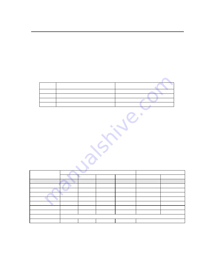
The following table shows how the switch positions relate to the ACR2000 card number
and I/O port addresses.
Note that Switch 4 should be left in the “OFF” position, unless using the Flash Bypass
Mode of operation. Flash Bypass Mode is selected when the user does not want to load
the program information from flash at power-up or reset. The card will not communicate
via the PC BUS at Card Number 15, so after the board is powered-up or reset in Flash
Bypass Mode, the SW1 settings must be placed back to a valid card number. Serial
communications via the COM1 and COM2 communication ports on the ACRCOMM
module will recognize the card as Card Number 15. However, the card should be placed
back to a valid card number during normal operation.
Card SW1
Settings
Addresses
Number 4 3 2 1 Data Status
0
OFF
OFF
OFF
OFF
0x300
0x302
1 OFF
OFF
OFF
ON
0x304
0x306
2 OFF
OFF
ON
OFF
0x308
0x30A
3 OFF
OFF
ON
ON
0x30C
0x30E
4 OFF
ON
OFF
OFF
0x310
0x312
5 OFF
ON
OFF
ON
0x314
0x316
6 OFF
ON
ON
OFF
0x318
0x31A
7 OFF
ON
ON
ON
0x31C
0x31E
8-14 RESERVED
15
ON
ON
ON
ON
Flash Bypass Mode
Table 1.2 ACR2000 PC BUS Port Addresses
Содержание ACR2000
Страница 1: ...Automation p n YPM08117 ACR2000 Hardware Manual Effective October 7 2002...
Страница 2: ...This page intentionally left blank...
Страница 6: ...This page intentionally left blank...
Страница 12: ...ACR2000 Hardware Manual P N PM08117 2 This page intentionally left blank...
Страница 13: ...Chapter 1 ACR2000 Motherboard Hardware Set Up 3 CHAPTER 1 ACR2000 MOTHERBOARD HARDWARE SETUP...
Страница 20: ...ACR2000 Hardware Manual P N PM08117 10 ACR2000 MOTHERBOARD JUMPERS Figure 2 ACR2000 Digital Input User Circuit...
Страница 22: ...ACR2000 Hardware Manual P N PM08117 12 ACR2000 MOTHERBOARD JUMPERS Figure 3 ACR2000 Digital Output User Circuit...
Страница 33: ...Chapter 2 ACRCOMM Module Hardware Set Up 23 CHAPTER 2 ACRCOMM MODULE HARDWARE SETUP OPTIONAL...
Страница 45: ...Chapter 3 ACR2000 Specification 35 CHAPTER 3 SPECIFICATIONS...
Страница 48: ...ACR2000 Hardware Manual P N PM08117 38 This page intentionally left blank...
Страница 49: ...Chapter 4 ACR2000 Mechanical Drawings 39 CHAPTER 4 ACR2000 MECHANICAL DRAWINGS...
Страница 50: ...ACR2000 Hardware Manual P N PM08117 40 ACR2000 MECHANICAL DIMENSIONS Figure 6 ACR2000 Mechanical Dimensions...


