


12
Technical Data
Technical Data
Technical Data
Technical Data
07-02-12-02-EN-V1215.doc / Type:
638
113
●
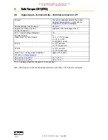
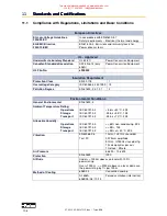
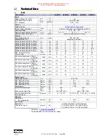
Signal Inputs and Outputs - Connection X120B resp. 120C
Additional Galvanic Separation from Power and
Control Circuit
Nominal Voltage of the In and Outputs
24 V DC +20% / -10%
Number of Outputs
Signal Outputs via OPTO Coupler
4
resistive load Imax. = 2A
inductive load max. 1Henry
I
out
.
Inductance Max. Switching
Frequency
1A
1H
1Hz
1A
0,1H
10Hz
0,33A
1H
10Hz
0,2A
0,5H
50Hz
short-circuit current limited by (5A)
over-heating protection, active
overvoltage clamping (50V); keyed
Number of Inputs
Signal Outputs via OPTO Coupler
4
L = 0...7 V DC or open
H = 15...30 V DC
Iin at 24VDC: 8 mA
Shortest Time for a Signal to All Inputs to Accept
the Signal in an Application:
> 1 ms
Damping of the Transfer from
Low to High (0-->24V):
default input:
200µs
Damping of the Transfer from
High to Low (24-->0V)
default input:
1000µs
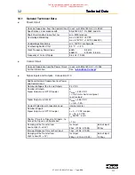
●
Digital Control
Current Control
Loop-Cycle-Time
105 µs
Settings
according to factory specifications or
motor data
Current Limits - Adjustment by:
speed control -menu
Analog Input
0..10V = 0..100%; can be standardized,
10Bit
Speed Control
Loop-Cycle-Time
105 µs
Settings
speed control menu
Differential Setpoint Input Analog
Resolution (including sign)
Usoll = 10 V, can be normed; Ri = 10k
14 bit
Digital Setpoint Input
via interfaces
Position Control
Loop-Cycle-Time
105 µs
This manual was downloaded on www.sdsdrives.com
+44 (0)117 938 1800 - [email protected]