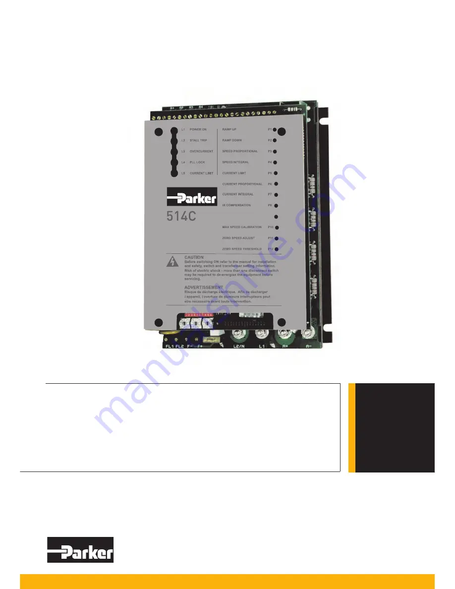
Parker 514C Скачать руководство пользователя страница 1

514C

DC Controller

HA463296 Issue 8
Technical Manual

aerospace

climate control

electromechanical

filtration
fluid & gas handling
hydraulics
pneumatics
process control
sealing & shielding

ENGINEERING 

YOUR 

SUCCESS.

This manual was downloaded on www.sdsdrives.com 

+44 (0)117 938 1800 - [email protected]

Содержание 514C

Страница 1: ... Manual aerospace climate control electromechanical filtration fluid gas handling hydraulics pneumatics process control sealing shielding ENGINEERING YOUR SUCCESS This manual was downloaded on www sdsdrives com 44 0 117 938 1800 info sdsdrives com ...

Страница 2: ...aken to ensure the accuracy of this document it may be necessary without notice to make amendments or correct omissions Parker Hannifin Manufacturing Limited cannot accept responsibility for damage injury or expenses resulting therefrom WARRANTY The general terms and conditions of sale of goods and or services of Parker Hannifin Europe Sarl Luxembourg Switzerland Branch Etoy apply to this product ...

Страница 3: ...ety and warning requirements of the application are met The user must analyze all aspects of the application follow applicable industry standards and follow the information concerning the product in the current product catalog and in any other materials provided from Parker or its subsidiaries or authorized distributors To the extent that Parker or its subsidiaries or authorized distributors provi...

Страница 4: ... used as a refer to Certification for the Inverter Component Relevant Apparatus Unit fitted Wall mounted Enclosure Application Area The equipment described is intended for industrial motor speed control utilising DC Shunt Wound or DC Permanent Magnet Motors Personnel Installation operation and maintenance of the equipment should be carried out by qualified personnel A qualified person is someone w...

Страница 5: ...orrectly installed All control and signal terminals are SELV i e protected by double insulation Ensure all external wiring is rated for the highest system voltage Thermal sensors contained within the motor must have at least basic insulation All exposed metalwork in the Inverter is protected by basic insulation and bonded to a safety earth RCDs are not recommended for use with this product but whe...

Страница 6: ...rocedure 3 1 Installation Precautions 3 1 Mechanical Installation 3 1 Installation Information 3 3 Electrical Installation 3 3 Requirements for UL Compliance 3 5 Chapter 4 Setting Up Commissioning 4 1 Option Switches 4 1 Potentiometers 4 2 Basic Setting up Procedure 4 3 Running Performance Adjustments 4 7 Chapter 5 Diagnostics and Fault Finding 5 1 Diagnostic Leds 5 1 Drive Trips 5 2 Diagnostic Te...

Страница 7: ...m either tachogenerator or armature voltage the feedback source being switch selectable A current loop within the speed loop always ensures that controlled levels of current are applied to the motor actual levels being scaleable via programmable switches Motor protection is provided by a Stall detection circuit which will remove current from the motor after approximately 60 seconds Controller prot...

Страница 8: ...ARY SUPPLY SELECTOR SWITCH 24 23 22 21201918 1716 15141312 11 10 9 8 7 6 5 4 3 2 1 L1 POWER ON L2 STALL TRIP L3 OVERCURRENT L4 PLL LOCK L5 CURRENT LIMIT RAMP UP P1 RAMP DOWN P2 SPEED PROPORTIONAL P3 SPEED INTEGRAL P4 CURRENT LIMIT P5 CURRENT PROPORTIONAL P6 CURRENT INTEGRAL P7 IR COMPENSATION P8 P9 MAX SPEED CALIBRATION P10 ZERO SPEED ADJUST P11 ZERO SPEED THRESHOLD P12 A1 A2 A3 A4 CONTROL TERMINA...

Страница 9: ...10V 100 Kohm Inputs Positive Trim Setpoint 0 to 10V 100 Kohm Negative Trim Setpoint 0 to 10V 100 Kohm Current Limit 0 to 7 5V 50 Kohm Current Demand 0 to 10V 100 Kohm Tachogenerator Input 0 to 350Vdc 220 Kohm Thermistor Microtherm Input 200 ohm Normal 1800 ohm Overtemperature 5 Kohm Outputs Setpoint Ramp 0 to 10V 5 mA Analogue Total Setpoint 0 to 10V 5 mA Speed 0 to 10V 5 mA Current Demand 0 to 10...

Страница 10: ...GS Nominal Armature Voltage Va 90 Vdc at 110 120 Vac 180 Vdc at 220 240 Vac 320 Vdc at 380 415 Vac Maximum Armature Current Ia 4A dc 10 8A dc 10 16A dc 10 32A dc 10 Armature Current Calibration 100 Ical 0 1 to 4A in 0 1A steps 0 1 to 8A in 0 1A steps 0 1 to 16A in 0 1A steps 0 1 to 32A in 0 1A steps Nominal Motor Power Pm 1 125kW 2 25 kW 4 5 kW 9 kW at 320 Vdc Armature HP 11 2 HP 3 HP 6 HP 12 HP O...

Страница 11: ...Field Terminals FL1 FL2 F F Screw Terminals will accept 4mm2 stranded wire Terminal Tightening Torque 0 5 Nm 4 5 lbf in Power Terminals L2 N L1 A A M5 Studs with Clamp Terminal Tightening Torque 2 7 Nm 24 lbf in Earth Grounding Terminals M5 Cheese Head Screw Terminal Tightening Torque 7 1 Nm 63 lbf in ENVIRONMENTAL REQUIREMENTS Enclosure Chassis Mounting IP00 UL open type Operating Temperature 0 t...

Страница 12: ... 10V 1kHz AM No Change Power Interfaces Fast Transient Burst BS EN 61000 4 4 1995 2kV Self Recovery Bulk Current Injection ENV 50141 10V 1kHz AM No Change Emissions Port Phenomenon Test Standard Level Generic Standard Enclosure Port Radiated EN55011 Class B EN50081 1 1992 Power Port Conducted EN55011 Class B EN50081 2 1994 Notes These levels of performance are achieved when installed as specified ...

Страница 13: ...ABLE Auxillary AC Supply Mains Supply PE GRD Signal Ground 1 2 GND 1 It is recommended that the 0V common be connected to protective earth ground for safety reasons In a system comprising of more than one controller the 0V common signals should be connected together and joined to protective earth ground at one point only 2 Stall override link between terminals 14 and 15 required when using control...

Страница 14: ...ue Output 0 to 10V 0 to 100 Ramped Setpoint 5mA output S C protected T10 Positive Trim Speed Setpoint Input Analogue Input 0 to 10V 0 to 100 Speed approx 100 kohm T11 0V Common Analogue Digital Signal Common T12 Total Setpoint Sum Output Analogue Output 0 to 10V 0 to 100 Speed 5mA output S C protected T13 Setpoint Ramp Input Analogue Input 0 to 10V 0 to 100 Forward Speed 0 to 10V 0 to 100 Reverse ...

Страница 15: ...to 0V Overtemperature 5k approx T23 Zero Speed Output Zero Setpoint Output Digital Output 24V Stopped Zero Setpoint 0V Running Non zero setpoint 50mA Source Short Circuit Protected T24 24V 24V Supply Output 20mA For use on the drive only CAUTION The 24v supply from the drive terminal T24 is for use with the drive only It should be used with the RUN circuit terminal 5 to control the drives internal...

Страница 16: ...8 T21 Setpoint Input 3 Inverted Negative Trim Speed Setpoint I P A9 T17 Total Setpoint A10 T12 10V Reference A11 T14 10V Reference A12 T16 Common B1 T11 Tachogenerator Input B2 T1 Current Demand Isolate B3 Current Demand Output B4 T18 Auxiliary Current Demand Input B5 T18 Select Auxiliary Current Input B6 Auxiliary Current Limit Positive B7 Main Current Limit B8 T7 10V Reference B9 T14 Auxiliary C...

Страница 17: ... Switches Function 540 1 514C Speed Calibration No Yes SW1 2 Tachogenerator or Armature Voltage No Yes SW1 3 Zero Output Speed or Setpoint No Yes SW1 4 Current Bipolar or Modulus Yes S1 Yes S1 5 Ramp Isolate Yes S3 Yes SW1 6 Standstill Yes S2 Yes SWQ1 7 Current Demand Output or Current Demand Input No Yes SW1 8 Contactor Dropout on Overcurrent No Yes SW1 9 Standstill Comparator Source No Yes SW1 1...

Страница 18: ...inals TERMINAL FUNCTION DESCRIPTION NOTES L1 AC Input Line 1 Mains Supply Line 1 Input L1 L2 N AC Input Line 2 Neutral Mains Supply Line 2 Input or Neutral L2 N A Armature Positive Motor Armature Positive Output A A Armature Negative Motor Armature Negative Output A Ground Field Terminals TERMINAL FUNCTION DESCRIPTION NOTES F Field Negative Motor Field Negative DC Output 540 1 Terminal D7 F Field ...

Страница 19: ...CODING C COM P VA 50 A3 0V SIGNAL LED3 LED2 LED5 LIM IT CURRENT SYNC LED4 PLL 1 1 1 Z CUSTOM ER DIAGNOSTIC SOCKET P2 P1 20 LOGIC ENABLE STANDSTILL Z7 Z8 ARM ATURE VOLTAGE FEEDBACK ENABLE OUTPUT 1 17 18 POSITIVE TRIM SETPOINT SETPOINT SPEED P11 ZERO ADJ UST Z26 Z16 SPEED CALIBRATION Z27 21 SW1 6 INVERTED SETPOINT SUM ZERO OUTPUT SELEC T SW1 4 SW1 10 24 SW1 7 22 THERM ISTOR M ICROTHERM Z6 SW1 2 SW1 ...

Страница 20: ... Path DIL Switch Selectable External Current Demand I P Additional Current Demand Current Demand O P or Ext Current Demand I P Current Demand Connect Enable Input of External Current Demand Not Provided Armature Current Output External IR Compensation via Armature Current Output Internally provided Auxiliary Enable External Trip Enable Not Provided Ready Drive Ready Output Not Provided Stop Input ...

Страница 21: ... 1 FL1 FL2 F F L2 N L1 A A E B RAMP UP RAMP DOWN SPEED PROPORTIONAL SPEED INTEGRAL CURRENT LIMIT CURRENT PROPORTIONAL CURRENT INTEGRAL IR COMPENSATION MAX SPEED CALIBRATION ZERO SPEED ADJUST ZERO SPEED THRESHOLD L1 POWER ON L2 STALL TRIP L3 OVERCURRENT L4 PLL LOCK L5 CURRENT LIMIT P1 P2 P3 P4 P5 P6 P7 P8 P9 P10 P11 P12 SW2 SW3 SW4 ON 1 2 3 4 5 6 7 8 9 10 SW1 DIAGNOSTIC SOCKET Tenths Unit Tens PROD...

Страница 22: ...lter Watt Loss Overall Dimensions Fixing Centres Product Fixing Terminal L W H E A B C D 514C 04 CO389113 18W 264 165 45 240 253 120 210 148 4mm2 514C 08 CO389113 18W 264 165 45 240 253 120 210 148 4mm2 514C 16 CO389113 18W 264 165 45 240 253 120 210 148 4mm2 514C 32 CO389114 36W 264 165 70 240 253 120 210 148 6mm2 This manual was downloaded on www sdsdrives com 44 0 117 938 1800 info sdsdrives co...

Страница 23: ...ent form factor of 1 5 or less It is recommended that a armature choke be fitted where a form factor of less than 1 5 current cannot be guaranteed 3 Due to the earth leakage currents the controller and filter should be permanently earthed This can be achieved by either connecting two earthing conductors of the required value see table 3 1 or connecting one earthing conductor of at least 10mm2 4 Un...

Страница 24: ...0 50A fuse 60A U S CH390054 Motor 32A 16mm2 6AWG Ground 16mm2 6AWG ALL Field 3A 1 5mm2 16AWG LA054664 10A CH230014 TABLE 3 1 Recommended Cable Sizes Note The cable sizes shown are based on a Form Factor of 1 5 and an overload allowance of 110 giving a multiplier of 1 65 they are selected for the notional rating of each controller Smaller cable may be used if the controller is calibrated at a lower...

Страница 25: ...4 514C 08 UL Listed SMVV pressure wire connectors rated No 10 AWG copper must be used for Models 514C 16 Short Circuit Protection UL Listed fuses Class RK5 rated 250V ac or 600V ac as appropriate depending on the rated input voltage of the drive 50A maximum must be installed upstream of the drive Short Circuit Rating Models rated more than 1Hp Suitable for use on a circuit capable of delivering no...

Страница 26: ...erator and armature voltage feedback General Purpose Switches SW1 3 Speed Feedback OFF Tachogenerator Feedback for Speed Control ON Armature Voltage Feedback for Speed Control SW1 4 Zero Output OFF Zero Speed Output ON Zero Setpoint Output SW1 5 Current Meter OFF Bipolar Output ON Modulus Output SW1 6 Ramp Isolate OFF Ramp Connected ON Ramp Isolated SW1 7 Standstill Logic OFF Disabled ON Enabled S...

Страница 27: ...tegral time constant Midway 540 1 P6 P5 I Limit Rotate Clockwise to increase Maximum Output Current With no additional connection to Torque Current Limit Terminal T7 the Upper Limit is 110 To achieve the 150 maximum connect T7 to 7 5V 90 Clockwise 540 1 P7 P6 Current Loop Proportional Optimises Current Loop Stability by increasing gain Midway 540 1 P8 P7 Current Loop Integral Optimises Current Loo...

Страница 28: ...If an air supply is available it is recommended to blow over the commutator Check the brushes are properly seated and that the brush spring tension is adequate If possible check that the motor and vent fan if fitted can be turned freely by hand Preparation MACHINE Check 1 That rotation of the motor in either direction will not cause damage 2 That nobody else is working on another part of the equip...

Страница 29: ...ng assumes the system to be a simple speed control drive and motor 1 When all the preceding steps are completed the auxiliary power supply can be connected to terminals A3 and A4 but do not connect the L1 and L2 main power supply at this stage Immediately check that the correct voltage appears between A3 and A4 2 Now check i The drive condition indicators these are 5 LED lamps at the top left corn...

Страница 30: ...circuit as shown in the basic wiring diagram WARNING DO NOT PROCEED FURTHER UNLESS THE RUN CIRCUIT AND CONTACTOR OPERATE CORRECTLY 7 Turn off all power supplies to the equipment and when the whole system is totally isolated and safe re connect the Main L1 and L2 supply 8 Turn on Auxiliary single phase supply 9 Turn on Main L1 and L2 supply 10 Turn the Speed Setpoints to zero so that the Total Setp...

Страница 31: ...d Tachogenerator Polarity 16 When the Main Current Limited P5 set to about 20 FLC slowly increase the Total Setpoint voltage to 1 volt terminal T12 Diagnostic 15 The motor should now run at about 10 Full Speed Note When correctly connected and operating normally at constant speed the Speed Feedback voltage Diagnostic 16 will be equal to the Total Setpoint voltage Diagnostic 15 but is of the opposi...

Страница 32: ...ment P6 and P7 1 With all power supplies disconnected disconnect the field wires from terminals F and F labelling each wire clearly so that it can later be reconnected with the correct polarity Connect the Stall Override terminal T15 to 10v NOTE i It is now possible to operate the motor in a stalled condition Great care must be taken not to damage the motor by overheating If the motor is fitted wi...

Страница 33: ...o terminals F and F ensuring that they are replaced in their original positions i e with correct polarity Remove any mechanical devices previously used to lock the motor shaft Speed Loop Adjustment P3 and P4 1 If the Speed Setpoint is applied via the setpoint ramp turn P1 and P2 fully clockwise minimum ramp time Set the Speed Setpoint to zero Switch the Diagnostic Unit to position 16 so that the O...

Страница 34: ...Electronic Phase Lock Loop is Synchronised LED5 CURRENT LIMIT Illuminated when the Controller is in Current Limit and Speed Control is lost i e a stall condition after 60 seconds the controller will trip P1 P2 P3 P4 P5 P6 P7 P8 P9 P10 P11 P12 SW1 SW2 SW3 SW4 A1 A2 A3 A4 1 ON 1 2 3 4 5 6 7 8 9 10 DIAGNOSTIC LEDS L1 POWER ON L2 STALL TRIP L3 OVERCURRENT L4 PLL LOCK L5 CURRENT LIMIT RAMP UP RAMP DOWN...

Страница 35: ...it is possible to prevent the stall trip by using the Stall Override Terminal 15 DIAGNOSTIC TEST POINT DESCRIPTIONS Test Node Description Condition Voltage 1 Internal 15V Supply Auxiliary Supply On 15V 0 15V 2 External 10V Supply Auxiliary Supply On 10V 0 025V 3 External 10V Supply Auxiliary Supply On 10V 0 025V 4 Internal 15V Supply Auxiliary Supply On 15V 0 15V 5 Drive Enable Enable 10V to 24V T...

Страница 36: ...oop Out Run Steady State up to 10V Stopped or Disabled 0V 20 No Connection 21 No Connection 22 No Connection 23 Current Limit Terminal Open Circuit 110 5 5V Terminal T7 7 5V or greater 150 7 5V 24 Main Current Limit T7 7 5V or greater P5 Maximum 150 Current 7 5V P5 Minimum 0 5 Current 0 025V 25 Total Current Demand Run Transient up to 7 5V Terminal T7 7 5V or greater 150 Positive Bridge at 150 Lim...

Страница 37: ... Run Enable Signal not present Check Control Circuit Wiring Command No Speed Setpoint Check Total Setpoint terminal T12 Check Setpoint Pot meter Wiring If using the Setpoint Ramp Input T13 check SW1 6 is OFF No Armature Current Check P5 adjustment External Current Limit Potentiometer setting wiring if used No Field Check Field AC Supply and Field connections Motor Jammed Free Obstruction Motor Run...

Страница 38: ...ter Check Terminal 13 or 10 as appropriate Motor runs with Zero Setpoint Zero Speed Offset Adjustment Adjust P11 to give Zero Speed Motor Speed unstable at Constant Stability Adjustment See General Running performance adjustments Chapter 4 Speed Setpoint Current Stability Adjust Current Loop Stability Potentiometers P6 P7 Speed Stability Adjust Speed Loop Stability Potentiometers P3 P4 IR Compensa...

Страница 39: ...e NOTE THE SPECIFIED EMC EMISSION AND IMMUNITY PERFORMANCE OF THIS UNIT CAN ONLY BE ACHIEVED WHEN THE UNIT IS INSTALLED TO THE EMC INSTALLATION INSTRUCTIONS GIVEN IN THIS MANUAL According to S I No 2373 which implements the EMC directive into UK law the requirement for CE marking this unit falls into two categories 1 Where the supplied unit has an intrinsic direct function to the end user then the...

Страница 40: ...f the existing installation NOTE WHEN TWO OR MORE EMC COMPLIANT COMPONENTS ARE COMBINED TO FORM THE FINAL MACHINE SYSTEM THE RESULTING MACHINE SYSTEM MAY NO LONGER BE COMPLIANT EMISSIONS TEND TO BE ADDITIVE IMMUNITY IS DETERMINED BY THE LEAST IMMUNE COMPONENT UNDERSTAND THE EMC ENVIRONMENT AND APPLICABLE STANDARDS TO KEEP ADDITIONAL COMPLIANCE COSTS TO A MINIMUM Applying for CE Marking for EMC We ...

Страница 41: ...ifin Manufacturing Limited address as below declare under our sole responsibility that the above Electronic Products when installed and operated with reference to the instructions in the Product Manual provided with each piece of equipment is in accordance with the relevant clauses from the following standard BSEN61800 3 2004 The above Electronic Products are components to be incorporated into mac...

Страница 42: ...ropriate materials in accordance with the valid environmental control laws The following table shows which materials can be recycled and which have to be disposed of in a special way Matrial Recycle Disposal metal yes no plastics material yes no printed circuit board no yes The printed circuit board should be disposed of in one of two ways 1 High temperature incineration minimum temperature 1200o ...

Страница 43: ... 353 0 1 466 6370 parker ireland parker com IN India Mumbai Tel 91 22 6513 7081 85 IT Italy Corsico MI Tel 39 02 45 19 21 parker italy parker com JP Japan Tokyo Tel 81 0 3 6408 3901 KR South Korea Seoul Tel 82 2 559 0400 KZ Kazakhstan Almaty Tel 7 7272 505 800 parker easteurope parker com MX Mexico Apodaca Tel 52 81 8156 6000 MY Malaysia Shah Alam Tel 60 3 7849 0800 NL The Netherlands Oldenzaal Te...

Отзывы: